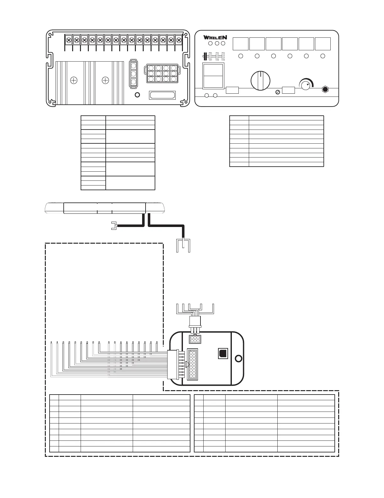
Example #2: Integrating a WeCan® Control Point Module into a 295SLS*6 System.
FUNCTION
Take-downs
Driver Alley Light
Passenger Alley Light
Traffic Advisor™ Left
Traffic Advisor Right
Low Power
Rear
Front + Rear
Front + Rear + Flashing Take-Downs
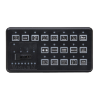
BUTTON
PB1
PB2
PB3
PB4
PB5
PB6
SS1
SS2
SS3
FUNCTION
Slide Switch #1
Slide Switch #2
Slide Switch #3
Push Button #1
Push Button #2
Push Button #3
Push Button #4
Push Button #5
Push Button #6
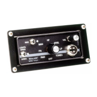
TERMINAL
1
2
3
4
5
6
7
8
9
10
11
12
13
14
15
PB#1
Activates
Terminal
6
SS
#1
SS
#2
SS
#3
PB#2
Activates
Terminal
7
PB#3
Activates
Terminal
8
PB#4
Activates
Terminal
9
PB#5
Activates
Terminal
10, 11, 12
PB#6
Activates
Terminal
13, 14, 15
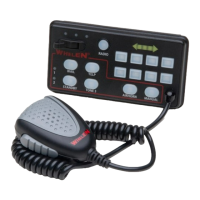
MAN
RAD
12
HORN
RAD
MAN 1
MAN 2
HF
T1
T2
T3
®
SPEAKERS
MIC VOL.
20 Amp Fuse
123456789101112131415
(TERMINALS)
1
2
3
3
2
1
6
5
4
9
8
7
12
11
10
COLOR
GREEN
GRN/WHT
GRN/BLK
WHT/RED
WHITE
YELLOW
WHT/VIO
WHT/GRN
WHT/ORG
FUNCTION
FRONT PATTERN 1
FRONT
FRONT
FRONT
DRIVER ALLEY
PASSENGER ALLEY
AUX
RIGHT TRAFFIC ADVISOR
CRUISE LIGHTS
PATTERN 2
PATTERN 3
PATTERN 4
Connects to...
Terminal
T 7 (PB#2)
T 8 (PB#3)
O
T 10 (PH#5)
OPTIONAL
2 (SS#2)
Optional
Optional
Optional
erminal
erminal
ptional
erminal
POS
1
2
3
4
5
6
7
8
9
COLOR
BLUE
BLU/WHT
BLU/BLK
WHT/BRN
WHT/BLK
WHT/BLU
RED/WHT
WHT/YEL
VIOLET
FUNCTION
REAR
REAR
REAR
REAR
TAKE DOWNS
FLASHING TD / ALLEY
OVERRIDE
LEFT TRAFFIC ADVISOR
LOW POWER
PATTERN 1
PATTERN 2
PATTERN 3
PATTERN 4
-
STEADY
Connects to...
Terminal 1 (SS#1)
Optional
Optional
Optional
Terminal 6 (PB#1)
Terminal 3 (SS#3)
Optional
Terminal 9 (PB#4)
Terminal 13 (PB#6)
POS
10
11
12
13
14
15
16
17
18
LIGHTBAR
Communication
Cable
Power
Cable
Pos. 1 - (GRN) Front Pattern 1
Pos.10 - (BLU) Rear Pattern 1
Pos. 2 - (GRN/WHT) Front Pattern 2
Pos.11 - BLU/WHT) Rear Pattern 2
Pos. 3 - (GRN/BLK) Front Pattern 3
Pos.12 - (BLU/BLK) Rear Pattern 3
Pos. 4 - (WHT/RED) Front Pattern 4
Pos.13 - (WHT/BRN) Rear Pattern 4
Pos. 5 - (WHT) Driver Alley Light
Pos.14 - (WHT/BLK) Take-downs
Pos. 6 - (YEL) Passenger Alley Light
Pos.15 - (WHT/BLU) Flashing T-D & Alley
Pos. 7 - (WHT/VIO) Aux
Pos.16 - (RED/WHT) Steady Override
Pos. 8 - (WHT/GRN) Traffic Advisor / RIGHT
Pos.17 - WHT/YEL) Traffic Advisor / LEFT
Pos. 9 - (WHT/ORG) Cruise Light
Pos.18 - (VIO) Low Power
9
8
7
6
5
4
3
2
1
18 17
16
15
14
13
12 11 10
321
654
Connect to an ignition
controlled circuit that
can accommodate an
additional 250mA load.
*
Pos. 1 - (RED) To +12VDC*
Pos.2-No
Connection
Pos. 3 - (BLK) To Ground
Pos. 4 - (GRN) COMM. A
Pos. 5 - (BLK/WHT) Shield
Pos. 6 - (GRY) COMM. B
RED - to +12VDC
(see lightbar manual for fusing)
BLACK - to CHASSIS GROUND
 Loading...