Installation Manual: GM LT1_A1R13E
Last Updated: February 12th, 2019
Page 10 of 36
www.whipplesuperchargers.com
18. The plastic cover cannot be removed due to firewall clearance, therefore you must loosen all the factory intake
manifold bolts (10) using a 10mm socket. Remove the intake manifold by lifting and sliding forward. Once the
intake manifold is out of the way, remove the plastic cover by removing the (4) plastic cable ties holding the wire
harness to the back of the cover.
19. Clean the intake manifold surface using carb cleaner or other like chemicals. Cover intake ports with masking tape
or duct tape.
20. Using a ½” breaker bar or long ½” socket, remove the stock belt by releasing the tension of the factory spring
loaded tensioner. Rotate in a counter-clockwise motion to release tension.
21. The SC assembly is shipped pre-assembled. For proper assembly, this must be disassembled.
22. Disassemble the SC assembly from the intake manifold by removing the (16) 6mm SHCS using a 5mm allen socket
(6 are upside down). [(10) 6mm x 22mm, (2) 6mm x 25mm, (2) 6mm x 55mm]. Lift the SC assembly up from
intake manifold, carefully letting the bypass valve actuator arm rotate out of the bracket.
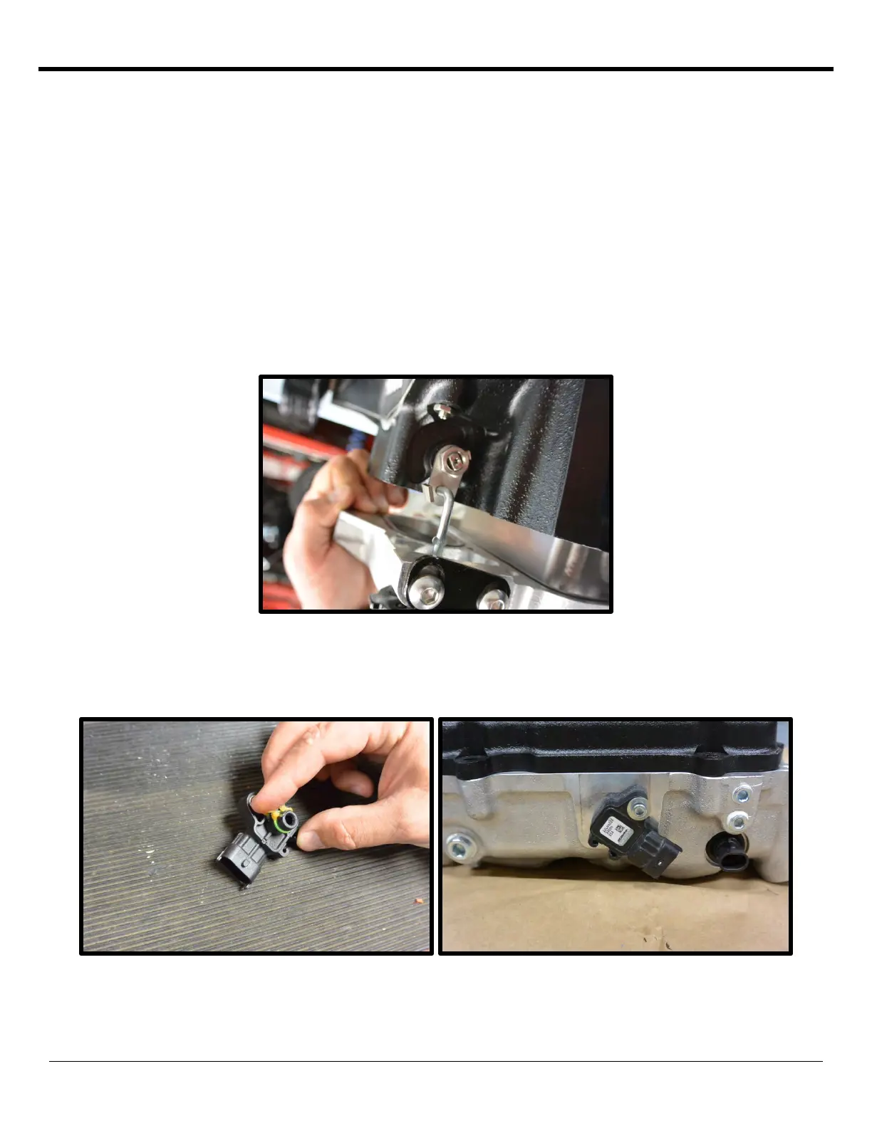
23. Install the stock MAP sensor into the back of the new intake manifold. Remove the red plastic cover from the
intake manifold, remove the pre-installed 10/32” SHCS and AN washer. Apply generous amount of grease to oring
on MAP sensor, carefully press into passage. Secure sensor with the 10/32” SHCS you previously removed. Apply
light amount of
Loctite™ (#648 green) threads to threads and torque to 32 in/lbs using a 5/32” allen socket.
 Loading...