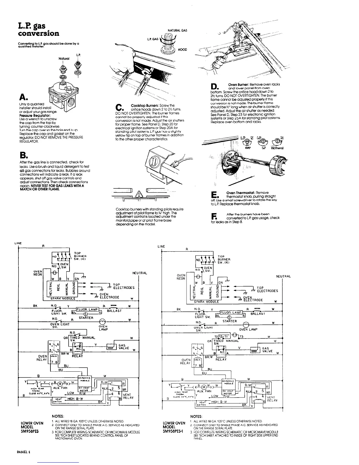
L.P. gas
convers2on
L.P.
Natural I
A.
Only 0 qualified
installer should inst
or adjust your gas range.
Pressure Regulator:
Use o wrench to unscrew
the ccl0 from the toD bv
turning counter-cl&k&
Turn the COD over so the hole end IS up
Replace the cap and gasket on the
regulator. DO NOT REMOVE THE PRESSURE
REGULATOR.
After the gas line is connected. check for
lwks. Use o brush and liquid detergent to test
all gas connections for leaks. Bubbles around
connections will indicate o leak. If o leak
appears. shut off gas valve controls ond
adjust connectlons. Then check connections
again. NEVER TEST FOR GAS LEAKS WITH A
MATCH OR OTHER FLAME.
LINE
R
t
NATURAL GAS
c.
Cooklop Burners: Screw the
onfrce hoods down 2 to 2% turns.
DO NOT OVERTIGHTEN The burner flames
cannot be properly adjusted If thrs
converSion is not made. Adjust the ar shutters
for proper flame See Panel D. Step 20 for
electrical ignition sysIems or Step 20A for
standing pilot systems. L P gos has o slightly
yellow tip on top of burner flames in oddrtron
to the other proper characterrstics
Ccoktop burnen with standing pilols require
adjustment of pilot flame to Yi’ high. The
adjustment control is located under the
manrfold pipe or at pilot flame base
depending on the model.
NE
3 :&ODES
-2
OVEN
ELECTRODE
w
NO.
, R
STARTER
w
“s’bt” L’GHT
w
OVEN
LAHP
3AL
D.
Oven Burner: Remove oven racks
and lower panel from oven
bottom Screw the orrfice hood down 2 to
2% turns. DO NOT OVERTIGHTEN. The burner
flame cannot be ad]usted properly if thus
coweRion IS not made. The burner flame
should be Yz” long when air shutter 1s correctly
adjusted Adjust the arr shutter OS needed
See Panel D. Step 23 for electronic ignition
systems or Step 25A for standrng prlot systems
Replace oven bottom and racks.
E.
Oven Thermostat: Remove
thermostat knob. pulling Straight
on, Use q small screwdriver to rotate the key
to L.P Replace thermostat knob.
After the burners hove bee”
converted to L.P gas usage. check
for leaks or in Step 0.
LINE
OYEN
NEON
NE
T :&ODES
3 OVEN
ELECTRODE
w
R -
w
BALLAST
NOTES:
NOTES:
LOWER OVEN
MODEL
SMPSBPES
1 ALL WIRES 18 GA 105-C UNLESS OTHERWISE NOTED
2 CONNECT ONLY TO SINGLE PHASE AC SERVICE AS INDICATED
ON THE RANGE SERIAL PLATE
3 FOR COMPLETE WIRING SCHEMATIC OF MICROWAVE MODULE
SEE TECH SHEET LOCATED BEHIND CONTROL PANEL OF
MICROWAVE OVEN
LOWER OVEN
1
ALL WlRES
18 GA 105°C UNLESS OTHERWISE NOTED
MODEL
2
CONNECT ONLY TO SINGLE PHASE
AC SERVICE
AS INDICATED
ON THE RANGE SERIAL PLATE
SM95BPES.1
3 FOR COMPLETE WIRING SCHEMATIC OF MICROWAVE MODULE
SEE TECH SHEET A”ACHED TO INSIDE OF RIGHT SIDE UPPER END
PANEL
rRAL



 To Next Page