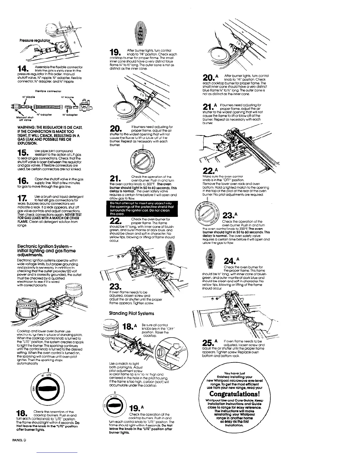
19.
After burner lights. turn control
knob to “HI” position Check each
cooktop burner for proper flame. The small
inner cone should hove o very distrncl blue
flame Yd” to Yz” long. The outer cone IS not OS
distinct OS the rnner cone.
Assemble the flexible connector
from the gas supply pipe to the
pressure regulator In this order: manual
shutoff valve. Ii” nipple. Yz” adapter, flexrble
connector. y?” adapter, and Yz” nipple.
20.A
After burner lights. turn control
knob to “HI”twsition. Check
each ccoktop burner for proper flame. The
small inner cone should have o very distrnct
blue flame yn” to yz” long. The outer cone is
not os distinct OS the inner cone.
21.
A If burners need odjustrng for
proper flame. adjust the air
shutter to the widest OpeninQ~thot wltl not
cause the flame to IiH or blow off of the
burner. Repeat OS necessorv wih each
burner
WARNING: THE REGULATOR IS DIE CAST.
IF THE CONNECTION IS MADE TOO
TIGHT, IT WILL CRACK, RESULTING IN A
GAS LEAK AND POSSIBLE FIRE OR
EXPLOSION.
20.
If burners need odjustlng for
proper flame, adjust the air
shutterto the widest opening that wilt not
cause the flame to IiH or blow off of the
burner. Repeat os necessary wth each
burner.
II
15.
Use pipe joint compound
resistant to the action of L.P gas
to seal all QOS connections. Check that the
shutoff valve is open between the regulator
and gas valves. If flexible connectors ore
used. be certain connectors ore not kinked
16.
Open the shutoff valve in the Qos
supply line. Wait 0 few minutes
for QOS to move through the gas line
21,
Check the operation of the
“\-‘1 burner. Push in and turn
-_- -.-,
the oven control knr
3b to 300°F The oven
burner should Ifok,
._ ..,..I In 50 to 60 seconds. This
delav Is normal. The oven sofetv valve
requires o certain time before it will open and
knob IS in the “OFF” position
Remove ihe lower oven rack and oven
bottom. Hold o lighted match to the opening
in the top of the pilot at the rear of the oven
burner No pilot adjustments ore required
17.
Use a brush and liquid detergent
to test all gas connections for
leaks. Bubbles around connectrons wrll
rndicate o teak. If o laak appears. shut off
gas valve controls and adjust connections.
Then check connections again. NEVER TEST
FOR GAS LEAKS WITH A MATCH OR OTHER
FLAME. Clean all detergent solution from
23.A
Check the operatron of the
oven burner Push in and turn
the oven control knob to 3w”F The oven
burner should liahl in 50 to 60 seconds. This
Check the oven burner for
proper flame Thrs flame
should be Yz” long. with inner cone of blulsh-
green. and outer mantle of dark blue. and
sho”,,jbeclea- ^^A^^O.^^L___^L^_ LI^
yellow tips, blo\... .~ _.
111 ..,~_, ,,-.,,- _ ,,--,-
occur.
range.
delay is norrr&The oven safety valve
requires o certain trme before It wilt open and
OIIOW the QOS t0 flow
Electronic lgnitlon System -
initial lighting and gas flame
adjustments.
Electronrc ignition systems operate wlthin
wide voltage limits. bul proper Qroundlng
ond polarity is necessary In addition to
checking that the outlet prowdesl20 volt
power and is correctly QrOUnded, the outlet
must be checked bv o auolified
' 24.A
Check the oven burner for
the proper tlome. Thus flame
should be Yz” lone with inner cone of btuirh-
green. and o”te&ontle of dark blue and
should be clean and son in character. No
Yellow tips. blowng or lining of the flame
electrician to see If h is v&d
with correct polarity
?%!hne needs to be
adjusted. loosen screw and
adjust the air shutter until the proper
should occur
flame appears. Tighten screw
Standing Pilot Systems
18 A Besure all control
-
knobs ore ,n the “OFF”
Ccoktop and lower oven burner use
electronic lgniten in place of standing pilots.
When the ccoktop control knob is turned to
the “LITE”position. the system creates Q spark
to light the burner This sparking continues
until the control knob is turned to the desired
settrng. When the oven control is turned on.
the sporkina wilt continue until oven orlot
ignites Thenthe sparking stops
positron Raise the
5
-
25.A
Ifo~enflameneedstobe‘ -
adjusted. loosen screw and
odyst the air shutter untrl the proper flame
appears Tighten saw Replace oven
botiom and bottom rack
Use ci match to light
both PIlOt IlQhtS Adjust
pllot adjustment screw
50 pilot flame tip is 6” to 318” htgh and
cente,ed i” the I.^,^ .^ u._^ ^,,^A L.. .^ ^-
If the flame IS to
Il”lrIII,,1~~~~“,,lu”rll,y
0 hlQh. Carbon (so@ wrll
crcc”m”Iore under the cooktop
~~- --.--,--
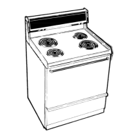
new Whtrlpool microwave eye-level
range. To get the most efwent
use from your new range, read your
Congratulations!
I
-
WhlrlDool Uw and Care Gutde. Keep I
Check the operatron of the
cooktop burners Push I” and
turn each control knob to “LITE” oo~111on. The
Instbllatlon Inshuclloru and Gutde
close lo rmge for eary re1emnce.
The lnshuctlorn will make
retrulolllng your WhIrlpool
range In another home
a( WLV as the nnl
18.
Check the operation of the
COOktop burners Push in and
hm each COnlrol knob to “LITE” wslilon.
The flame should Ii@ will+ A c-**n,+ h
Not leave the knob In the ‘LITE- postllon
aflef
burner Ilghts.
flame should light wilhrn 4 seconds. Do Not
leave the knob In the “UIE” position otter
burner Itghts.
PANEL D
 Loading...