EasyManua.ls Logo

Whirlpool MH1150XMQ User Manual

Whirlpool MH1150XMQ
12 pages
To Next Page IconTo Next Page
Page #1 background imageLoading...
Page #1 background image
TECH SHEET - DO NOT DISCARD PAGE 1
FOR SERVICE TECHNICIAN'S USE ONLY PART NO. 8184997/4619-651-98301
PRECAUTIONS TO BE OBSERVED BEFORE
AND DURING SERVICING TO AVOID POSSIBLE
EXPOSURE TO EXCESSIVE MICROWAVE ENERGY
a. Do not operate or allow the oven to be
operated with the door open.
b. Make the following safety checks on all
ovens to be serviced before activating the
magnetron or other microwave source, and
make repairs as necessary:
1. Interlock Operation
2. Proper Door Closing
3. Seal and Sealing Surfaces (Arcing,
Wear & Other Damage)
4. Damage to or Loosening of Hinges &
Latches
5. Evidence of Dropping or Abuse
c. Before turning on microwave power for any
service test or inspection within the
microwave generating compartments,
check the magnetron, waveguide or
transmission line and cavity for proper
alignment, integrity and connections.
d. Any defective or misadjusted
components in the interlock, monitor,
door seal, and microwave generation,
and transmission systems shall be
repaired, replaced, or adjusted by
procedures described in service manual
before the oven is released to the owner.
e. A microwave leakage check to verify
compliance with the Federal
performance standard should be
performed on each oven prior to release
to the owner.
f. Do not attempt to operate the oven if the
window area of the door is broken.
Electrical Shock Hazard
Disconnect power before servicing.
Replace all parts and panels before operating.
Failure to do so can result in death or electrical shock.
Display Likely Failure Condition Recommended Repair Procedure
Flashing
colon “:”
Power failure
After a power failure, the colon “:” will be flashing. Press any key to
end this indication. The colon will then be steady when in stand-by.
-F2-
Membrane switch failure Replace membrane switch. If problem persists, replace control board.
-F6-
Microwave relay failure
Check wiring to relay 4903 for short circuits. If wiring is OK, replace
control board.
FAILURE CODES/INDICATIONS
POWER OUTPUT MEASUREMENT
The power output of the magnetron can be
measured by the following tap water
temperature rise test:
Be sure oven cavity is clean and cool (not
used recently).
Low voltage will lower the magnetron output.
1. Fill a glass beaker with 1000 ml (32 oz.) of tap
water. Stir the water with a thermometer
(digital recommended) and record the
temperature. This starting temperature should
be between 10°C (50°F) to 24°C (75°F).
2. Place the beaker in the center of the oven.
Operate on HIGH power level for
60 seconds.
3. When done, stir the thermometer through
the water and record the temperature.
4. Subtract the cold water temperature from
the warm water temperature to get the
temperature rise. Normal range is as
shown in the following table:
Voltage
(VAC under load)
Temperature Rise
°C °F
120V 12 - 13 21 - 24
108V 10 - 11 18 - 19
Question and Answer IconNeed help?

Do you have a question about the Whirlpool MH1150XMQ and is the answer not in the manual?

Whirlpool MH1150XMQ Specifications

General IconGeneral
Capacity1.1 cu. ft.
Power Output1000 Watts
Control TypeElectronic
TurntableYes
Pre-Programmed SettingsYes
Child LockYes
Warranty1 Year Limited
TypeCountertop
Cooking ModesDefrost
ColorStainless Steel

Summary

Safety Precautions for Microwave Servicing

Microwave Exposure Prevention

Guidelines to avoid exposure to excessive microwave energy during servicing, including door checks and operational limits.

Power Output Measurement

Tap Water Temperature Rise Test Method

Procedure for measuring magnetron output power using a water temperature rise test.

Failure Codes and Indications

Common Error Code Diagnostics

Lists failure codes like flashing colon, -F2-, and -F6-, with associated problems and recommended repairs.

Parts Layout

Component Identification

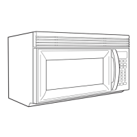
Visual representation of major microwave components and their locations.

PRIMARY, SECONDARY, AND MONITOR INTERLOCK SWITCH CHECKOUT PROCEDURE

Interlock Switch Testing

Procedure and expected results for checking primary, secondary, and monitor interlock switches in open and closed states.

TOUCH PANEL CONTINUITY DIAGRAM

Flex Circuit Continuity Test

Diagram and example for testing touch panel flex circuit continuity using an ohmmeter.

TOUCH PANEL AND MICROCOMPUTER BOARD TEST

Self-Diagnostic Routine

Instructions to initiate and perform a self-diagnostic test via the touch keypad.

TROUBLESHOOTING GUIDE

Initial Troubleshooting Steps

Essential preliminary checks before diagnosing microwave circuitry, including voltage and wiring.

MICROWAVE COOKING SCHEMATIC

Circuit Diagram for Cooking Mode

Detailed schematic illustrating the electrical connections during microwave cooking operation.

BLOWER FAN TURNS ON AUTOMATICALLY SCHEMATIC

Fan Auto Operation Circuit

Circuit diagram showing the automatic operation of the blower fan.

BLOWER FAN ON LOW SCHEMATIC

Low Speed Fan Circuit

Circuit diagram for the blower fan operating at low speed.

MICROWAVE PLUGGED IN - TIME OF DAY DISPLAYED SCHEMATIC

Standby Mode Circuit

Circuit diagram illustrating the microwave when plugged in and displaying the time of day.

DOOR OPEN - CAVITY LIGHT IS ON SCHEMATIC

Door Open Cavity Light Circuit

Circuit diagram showing the cavity light activation when the microwave door is opened.

COOKTOP LIGHT ON HIGH SCHEMATIC

High Speed Cooktop Light Circuit

Circuit diagram detailing the cooktop light operation at high intensity.

COOKTOP LIGHT ON LOW (NIGHT LIGHT) SCHEMATIC

Low Speed Cooktop Light Circuit

Circuit diagram illustrating the cooktop light operation at low intensity (night light).

COMPONENT TESTS

High Voltage Transformer Test

Procedure and expected resistance values for testing the H.V. Transformer windings and grounding.

Magnetron Test

Tests for magnetron seal integrity, filament terminal resistance, and filament to chassis resistance.

H.V. Capacitor Test

Procedure for discharging and measuring resistance of the H.V. Capacitor terminals.

H.V. Diode Test

Continuity testing for the H.V. Diode in both forward and reverse directions.

COMPONENT TESTS (Continued)

Turntable Motor Test

Resistance measurement procedure for the turntable motor.

Hood Fan Motor Test

Resistance measurement procedure for the hood fan motor at high and low speeds.

Thermostat Tests

Continuity testing for Cavity, Magnetron, and Exhaust Fan thermostats.

Related product manuals