Instructions
(Translation of the original instructions)
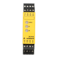
SNO 4083KM
Wieland Electric GmbH
Brennerstraße 10-14
D-96052 Bamberg
Tel. +49 (0) 951 / 9324 -0
Fax +49 (0) 951 / 9324 -198
www.wieland-electric.com
Doc. # BA000773 – 11/2014 (Rev. H) SNO 4083KM EN 8
Basic device for EMERGENCY STOP and safety door applications
• Basic device according to EN 60204-1:2007 and EN ISO 13849-1:2007 for single or
two-channel EMERGENCY STOP monitoring.
• PL e / category 4 according to EN ISO 13849-1:2007
• SILCL 3 according to DIN EN 62061:2005
• Stop category 0 according to DIN EN 60204-1
• Manual or automatic start
• With / without crossover detection
• Feedback circuit for monitoring external contactors
• Three enabling current paths, one messaging current path
• Evaluation unit for BWS 4 according to EN 61496-1
• Usage according to EN 81-1 and EN 50156-1
• For connection in series with a pressure sensitive mat according to EN 1760-1
Device versions
SNO 4083KM-A DC 24 with screw terminals, pluggable
SNO 4083KM-A AC 115-230 V with screw terminals, pluggable
SNO 4083KM-C DC 24 V with spring-loaded terminals, pluggable
SNO 4083KM-C AC 115-230 V with spring-loaded terminals, pluggable
Front view
Supply LED green, power supply indicator
K1, K2 LED green operating and status display for relays K1, K2 and the
safety circuits.
SAFETY REGULATIONS
Installation, commissioning, modification and retrofitting
must only be performed by a qualified electrician.
• Disconnect the device / the system from the power supply
before starting work. In the case of installation and system
errors, mains voltage can be present on the control circuit in
the case of non-galvanically isolated devices.
• Observe the electrotechnical and professional trade associa-
tion safety regulations for installation of the equipment.
• Opening the case or other manipulation voids any war-
ranty.
• In the case of improper use or any use other than for the
intended purpose, the device must no longer be used and
any warranty claim is void. Invalidating causes can be:
strong mechanical loading of the device, such as occur
when falling or voltages, currents, temperatures, humidity
outside the specifications.
• Always check all safety functions in accordance with the
applicable regulations during initial commissioning of your
machine / system and observe the specified inspection
cycles for safety devices.
WARNING
Take the following safety precautions before starting
installation / assembly or dismantling:
1. Disconnec
t the device / the system from the power
supply before starting work.
2. Secure the machine / system against being switched on
again.
3. Confirm that no voltage is present.
4. Ground the phases and short to ground briefly.
5. Cover and shield neighbouring live parts.
6. The devices must be installed in a switch cabinet with a
protection class of at least IP54.
• Limited contact protection! Protection class according to
EN 60529:
− Case / terminals: IP40 / IP20.
− Finger-proof according to EN 50274.
1 Proper use
The devices are safety switching devices. They must only be
used as components of safety equipment on machines that is
intended for the protection of persons, material, functions and
machinery.
2 Function
The device is a two-channel safety switching device for EMER-
GENCY STOP equipment according to EN 60204-1. It performs
self-monitoring during each ON-OFF cycle and is equipped with
positively driven relays. The device is suitable for connection in
series with short-circuiting pressure sensitive mats, pressure
sensitive bumpers or switching edges with 4-wire technology
(without a monitoring resistor).
Basic function: After applying the supply voltage to the
terminals A1/A2 and closed safety inputs, the enabling current
paths are closed when a valid reset signal is established at S34.
The enabling current paths are opened when the safety inputs
are opened / de-energized.
Operating modes / System functions
• Single-channel or two-channel actuation
• With or without crossover detection
• Manual start (triggering with falling edge)
• Automatic start
• Evaluation of signal transmitters featuring equivalent or non-
equivalent switching