CH FREQ Switch Settings
NO. (MHz) 1 2 3 4 5 6 7 8
CH 13 72.100 DN UP DN UP DN DN DN DN
CH 18 72.300 DN UP DN UP UP DN DN DN
CH 23 72.500 DN UP DN UP DN DN UP DN
CH 28 72.700 DN UP DN UP UP DN UP DN
CH 33 72.900 DN UP DN UP DN DN DN UP
CH 38 74.700 UP DN DN UP UP DN DN UP
CH 43 75.300 UP UP DN UP DN DN DN DN
CH 48 75.500 UP UP DN UP UP DN DN DN
CH 53 75.700 UP UP DN UP DN DN UP DN
CH 58 75.900 UP UP DN UP UP DN UP DN
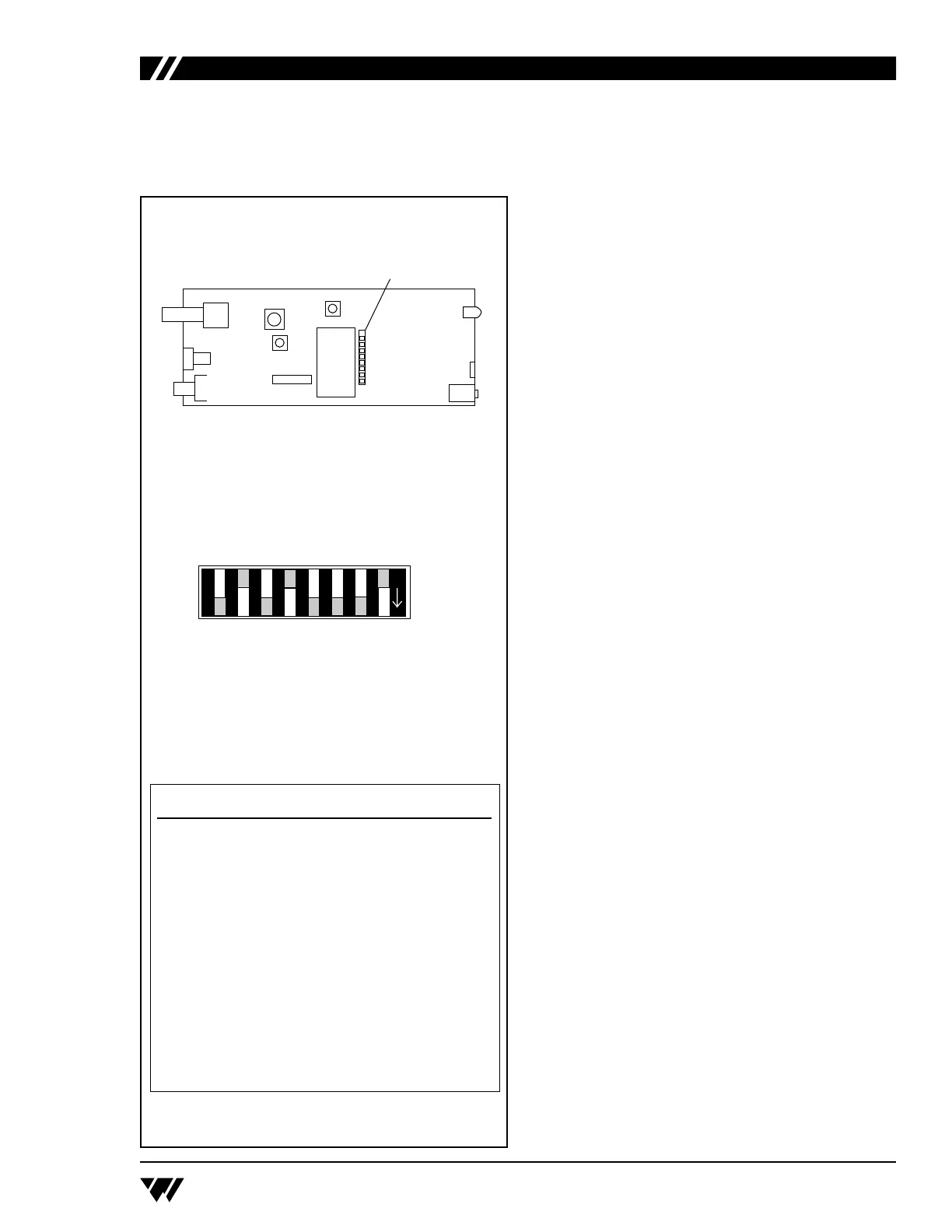
T17 Selector Switches
T17 Switch Settings Table
Location of T17 Selector Switches
Warranty
The Williams Sound T17 Transmitter and R19/
R19-4/R19-6 Receivers are warranted against
defects in workmanship and materials for FIVE
YEARS.
Microphones, earphones, cables, carry cases,
rechargeable batteries and chargers are warranted
against defects in workmanship and materials for 90
DAYS.
This warranty does not extend to intentional or
accidental physical damage.
This warranty applies only to products returned to
W
illiams Sound for service. To return a product for
service, call 1-800-843-3544 and request a Return
Authorization (RA) number.
 Loading...