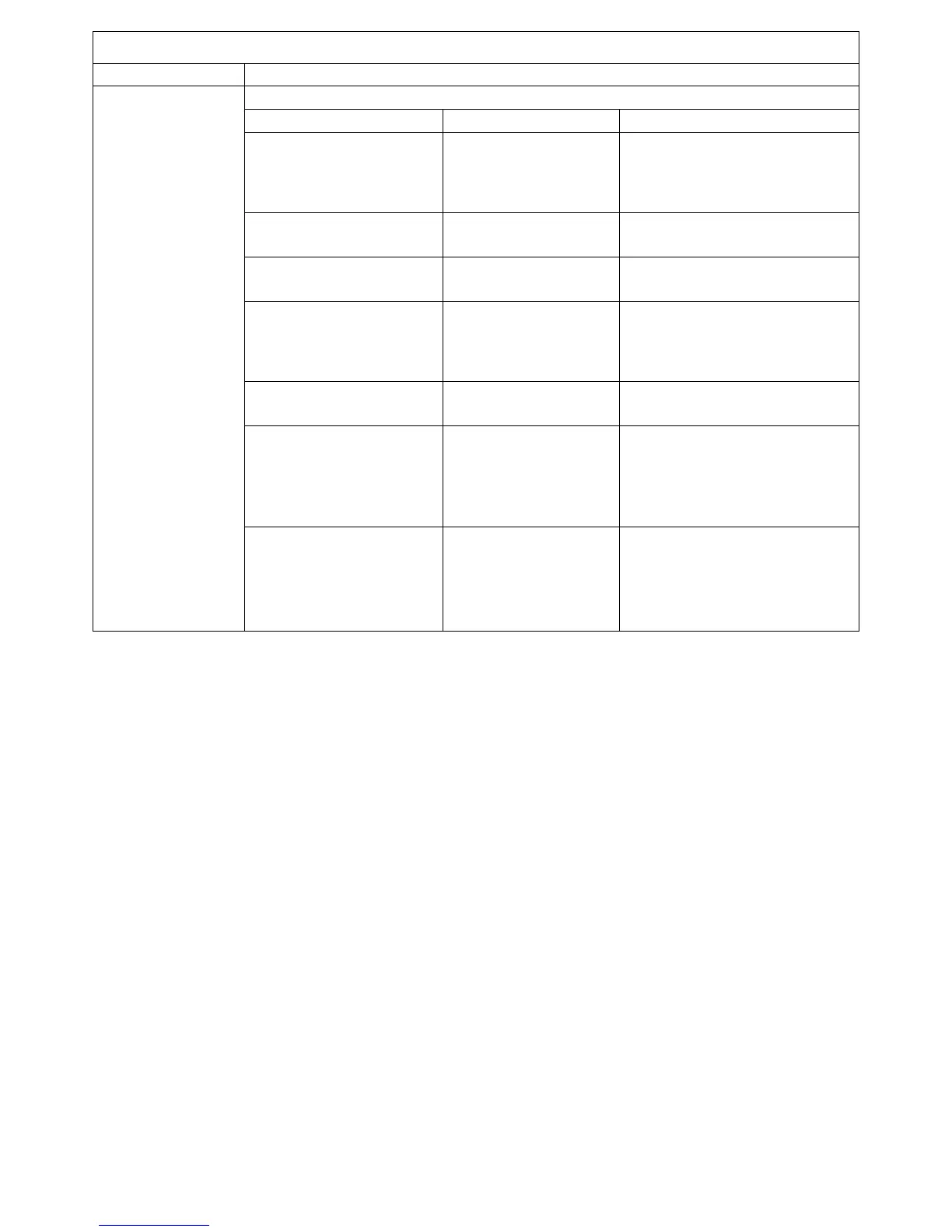
SOUND BOARD DIAGNOSTICS
SYMPTOM TEST & PROCEDURES
CHECK SOUND SELECT INPUTS
TEST TOOL CONDTION & REMEDY
Sound board connector
10P3/J3-2 to 7
Logic Probe (Game on
and in test 4)
•
PULSING - Proceed.
•
LOW - check jacks, foils.
•
STILL LOW - Perform ROM
board checkbox below.
SR1 DIP resistors
R3 to R9
VOM - Reading ohms
(game off)
•
ALL 4.7K - Proceed.
•
ANY OPEN - replace SR1.
C3 to C9 VOM - Reading ohms
(game off)
•
ALL OK - Proceed.
•
ANY SHORTED - replace bad.
IC 5-1, IC 7-14
(power pins)
Logic Probe (Game on
and in test 4)
•
HIGH - Proceed.
•
LOW - Replace C19 (IC5) or C21
(IC7).
•
STILL LOW - Replace bad IC.
IC5-2, 4, 6, 10, 12, 15
IC7-4, 6
Logic Probe (Game on
and in test 4)
•
PULSING - Proceed.
•
LOW - Replace bad chip.
IC10-18, 19
(PIA)
Logic Probe (Game on
and in test 4)
•
PULSING - Proceed.
•
LIFT C20 - Retest.
•
PULSING NOW - Replace C20.
•
STILL LOW - Replace IC6,
retest.
MISSING SOUNDS
NO SOUND-STEP 1
(ASSUMPTION:
INPUT SECTION
FAILURE)
IC10-10 to 17
(PIA)
Logic Probe (Game on
and in test 4)
•
PULSING - Proceed.
•
SOME LOW Replace IC.
•
ALL LOW - Lift C31, retest.
•
PULSING NOW - Replace C31.
•
STILL LOW - Replace IC
NOTE: In cockpit model games where no sounds are produced from either sound board, disconnect both 9-pin connectors from
one board and then the other. This isolates faults to a single Sound Board. If sounds are still nit produced from either board
check ROM Board outputs on page 19 first.