Model GL indirect-fired water heaters — Product Manual
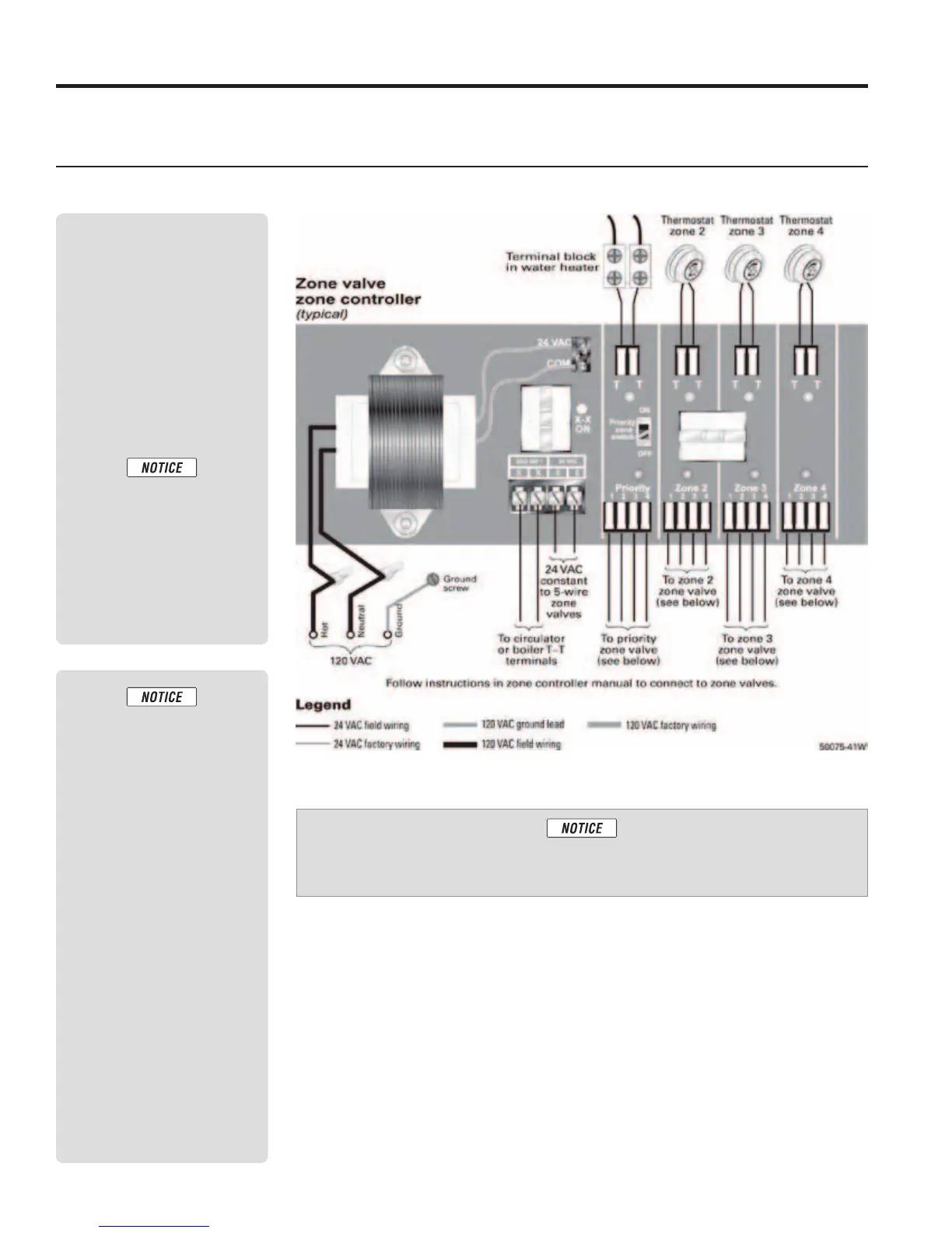
Wiring — zoning with zone valves
Notes
• Also refer to the zone con-
troller manual for further
details.
• Refer to Wiring require-
ments on page 20.
System piping
• Figure 9, page 13
• Figure 10, page 14
Install all zone valves per valve
manufacturer’s instructions.
1. This drawing is conceptual
only. It shows represen-
tative components and
wiring. Williamson-Ther-
moflo does not represent
that this drawing meets
any particular mechani-
cal or building codes. The
installer is responsible
for inclusion of all re-
quired safety devices, or
other miscellaneous pip-
ing hardware not shown
on drawing. The installer
is responsible for proper
sizing / selection of all
hardware shown on this
diagram.
2. Follow component manu-
facturer’s instructions for
installation of all items
shown.
3. See boiler manual for spe-
cific details on installing
the boiler.
Typical wiring — zoning with zone valves — DHW priority with zone valve zone controller
:
apply the drawings in this manual. Refer only to the boiler manual.
Part number GL-E224-ADOC 0413
22



 To Next Page