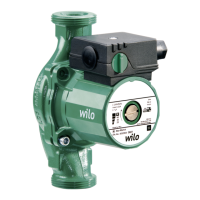
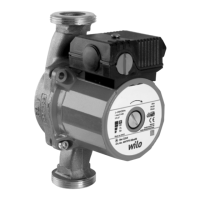
The Wilo-Star-Z/-ZD series of circulation pumps are specifically designed for domestic hot water circulation systems, ensuring corrosion resistance to all constituents in drinking water due to their material selection and construction. These glandless pumps consist of a hydraulic system and a motor with a terminal box. All rotating parts, including the motor rotor, are in contact with the fluid, eliminating the need for a wear-prone shaft seal. The fluid lubricates the plain bearings and cools both the bearings and the rotor. Motor protection is not required, as the motor is blocking-current proof, meaning even maximum overload current cannot damage it.
Function Description:
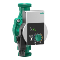
The pump types Z 25/6 and ZD 25/6 feature a rotary knob on the terminal box for manual switching between three speed stages (1 – 2 – 3). The lowest speed stage operates at approximately 40% to 50% of the maximum speed, resulting in a 50% reduction in current consumption.
For double pumps (Star-ZD), two identical motor impeller units are installed within a common pump housing, which includes an integrated switchover valve. Each pump can operate individually, or both can run simultaneously in parallel. Operating modes include main/standby or parallel/peak-load operation. Individual units can be configured for different capacities, allowing the double pump to adapt to specific operating situations. A corresponding switchgear is required for controlling these different operating modes.
Important Technical Specifications (for Wilo-Star-Z 25/6):
- Connection voltage: 1 ~ 230 V ±10% or 3 ~ 400 V ±10%
- Mains frequency: 50 Hz
- Protection class IP: See rating plate
- Motor speed: See rating plate
- Water temperature at max. ambient temperature +40 °C: +2 °C to +65 °C
- Max. ambient temperature: +40 °C
- Max. operating pressure: 10 bar (1000 kPa)
- Minimum inlet pressure (at +40 °C/+65 °C): 0.05 bar / 0.2 bar (5 kPa / 20 kPa). These values apply up to 300 m above sea level; for higher altitudes, add 0.01 bar/100 m increase in altitude. Maintaining the minimum inlet pressure at the suction port is crucial to prevent cavitation noises.
- Port-to-port length: 140 mm / 180 mm
- Variable speed control: 3 stages
Usage Features:
- Installation: The pump should only be installed after all welding and soldering work is complete and the pipe system has been flushed. It should be mounted in an easily accessible location for inspection and dismantling. In domestic hot water circulation systems, a non-return valve must be installed on the pressure side. Shut-off valves should be installed upstream and downstream to facilitate pump replacement.
- Motor Housing Orientation: The motor housing can be rotated after loosening its attachment screws to position the terminal box as needed (Fig. 5). Generally, the motor head should be turned before the system is filled. If turning the motor head in an already filled system, do not pull it out of the pump housing; apply slight pressure to the motor unit to prevent water leakage.
- Condensate Drain: Ensure condensate drain openings remain uncovered during thermal insulation work (Fig. 3, item 2).
- Flow Direction: Direction arrows on the pump housing and insulation shell (accessories) indicate the flow direction (Fig. 3, item 1).
- Electrical Connection: Electrical connections must be performed by qualified personnel according to local regulations. Always disconnect the power supply before any work. The connection cable should be routed to avoid contact with the piping or pump/motor housing. For side-mounted terminal boxes, the cable feed-in should always be from below (Fig. 5).
- Venting: The pump rotor chamber vents automatically after a short operating period. Brief dry running will not harm the pump. If manual venting is necessary (Fig. 9), switch off the pump, close the shut-off device on the pressure side, carefully unscrew the venting screw, push the pump shaft back several times with a screwdriver, protect electrical parts from water, then switch on the pump. After 15-30 seconds, screw the venting screw back in and reopen the shut-off device.
- Speed Adjustment: Speed is adjusted via the rotary knob on the terminal box (Fig. 8). For double pumps operating simultaneously, both pumps must have identical selected speeds.
Maintenance Features:
- Safety First: All maintenance and repair work must be carried out by authorized and qualified personnel. The pump must be electrically isolated and secured against unauthorized re-activation.
- Cable Damage: Any damage to the connection cable should only be repaired by a qualified electrician.
- Troubleshooting: The manual provides a troubleshooting guide for common faults (e.g., pump not running, noisy pump) with corresponding causes (e.g., electrical fuse defective, motor blocked, cavitation) and remedies (e.g., check fuses, check voltage, replace condenser, unblock rotor, increase system suction pressure). If a fault cannot be remedied, contact a specialist technician or Wilo's after-sales service.
- Spare Parts: Spare parts can be ordered from local specialist retailers or Wilo's customer service. All data from the rating plate should be provided with every order to avoid incorrect orders.
- Disposal: Proper disposal and recycling of the product prevent environmental damage and health risks. The pump should not be disposed of with household waste. Information on recycling can be found at www.wilo-recycling.com.