9
English
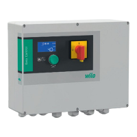
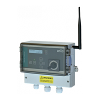
2.5. Settings
Todisplaymenuoptionsusenavigationkeys▲
and▼accordingtothefollowingscheme:
• Mainscreen-▲-Pump’sstartupmeter-▲-
Firstmenulevel-▲-Subsequentkeypressmenu
scrolling levels from 1 upwards.
• Mainscreen-▼-Lastmenulevel-▼-Subse-
quent key press menu scrolling levels from the
last level down.
If no key is pressed, then after 8 seconds the
menu will be closed.
The upper line of the each display shows the
name of the option, while the lower line shows
itssettingswhichcanbemodied.Inorderto
change a settings press “OK”. The current name
oftheoptionwillstarttoash.Thisallowstoset
upparameterswithnavigationkeys▲and▼.If
you hold one of the keys pressed for longer, the
value being set will change more rapidly. If you
press the key “OK” again, the new value will be
saved.
The table below displays all the menu options
alongwithexplanations.
Upper line of
display
Range of
settings
Explanation
Level measurm. internal
sensor
Liquid level measured with
hydrostatic pressure or
sparge pipe.
4-20
sensor
1.0m
Liquid level measured with
externalsensor
(0-1mrange).
4-20
sensor
2.0m
Liquid level measured with
externalsensor
(0-2mrange).
4-20
sensor
2.5m
Liquid level measured with
externalsensor
(0-2.5mrange).
4-20
sensor
4.0m
Liquid level measured with
externalsensor
(0-4mrange).
oat
switches
Liquid level measured with
oatswitches.
STOP level 0 - 91 cm Level at which the pump
turns off.
Readiness level 3 - 94 cm Level sent to the central
unit.
START level 6 - 97 cm Level at which the pump
turns on in case of no radio
communication, after
exceedingthetimeofno
communication.
High level 9 - 100 cm When the set level value is
exceededrelaycontactsof
the collective failure report
system and high level relay
are switched on.
Minimum
current
0 - 12 A When the pump’s current
falls below the set value,
the message “Dry run” will
be displayed, and after the
expirationofadjustedtime
(“Dryruntime”),thedevice
will turn the pump off and
report a failure. The pump
can be turned on again
after the failure is deleted
with the “OK” key. Current
of the pump decrease if
there is no liquid in the
tank or if the delivery pipe-
line is clogged.
Maximum
current
0 - 12 A If the pump’s current
exceedsthesetvalue,the
message “Overcurrent” will
be displayed. If this state
remains unchanged for a
speciedperiodoftime,
the device turns the pump
off and reports a failure.
The pump can be started
again after acceptance is
made with the “OK” key.
Dry run time 5 - 180 s Indicates how long the
pump is going to work
after the pump’s current
falls below the set value
of “Minimum current”.
After this period of time
there will be a break in the
pump’s work, or it will be
stopped in failure mode.
Pause time 5 - 15 min The time of the break in
the pump’s work after it is
stopped as a result of a dry
run. The time remaining till
the end of the break will be
displayed. No break occurs
if the value of the setting
“Dry run cycles”
is 1.
Dry run cycles 1 - 5 Number of work cycles
at the dry run state, after
which the pump is stopped
and the failure is reported.
Start delay 0 - 240 s Delay of pump’s start up
after the power supply
voltagedecays–thepump
can be turned on after a
speciedperiodoftime.
The display shows the
time, which remains to
the pump’s start up. This
setting is to prevent pumps
inunitssituatednextto
each other from simultane-
ous startup after decay of
voltage.
 Loading...