3
1 General
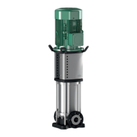
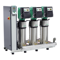
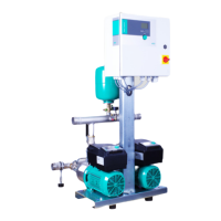
The SCe booster set is a 2-3 pump pressure
boosting system designed for maintaining water
pressure in domestic, commercial and industrial
applications using frequency converter driven,
variable speed pumps.
ATTENTION! Installation and commissioning by
qualied personnel only!
2 Safety
Any works carried out on the SCe booster sets
must be completed by a qualied person. Failure
to comply to any of the information in this manual
may cause potential hazards to people and the
environment and may void the warranty.
Operators must be fully aware of all functions of
the booster set and any risks associated. For more
information on training please contact Wilo Ph:
01283 523 000
WARNING! Local regulations must be complied
to when installing and maintaining the booster
set
2.1 Symbols and Signals
DANGER! Extremely dangerous situation. The non-
observance could cause death or serious injuries.
WARNING! The user may suffer from injuries
(serious). The mention of warning involves that
personal (serious) injuries may happen when
precautions are not observed.
ATTENTION! Damage could be caused to the pump
or installation. The mention of attention is used
to indicate that by ignoring the relevant safety
instructions, damage could be caused to the pump
or its operation.
NOTE - Useful remark for product handling. Any
possible difculty is mentioned.
2.2 Modication and Spare Parts
Modications to the booster are prohibited and
will invalidate the warranty. Wilo approved spares
must be used at all times. For information on
spares see section 10 Spares of this manual or
contact spareparts.uk@wilo.com or Ph: 01283
523 000
3 Transport and Storage
SCe booster must always be transported by pallet
and moved with appropriate lifting equipment.
Booster must be stored in a dry environment
between –25 °C to +55 °C.
NOTE – If stored for future installation lm
wrapping must not be removed and must be
stored in a dry environment
4 Description and Operation
4.1 SCe Controller General (single and three
phase)
The Smart Control (SCe) controller is used to
maintain the pressure in a system. Using a
programmable set point and a 4-20mA pressure
transducer on the discharge manifold. When
demand is required, and the pressure drops below
the set point, the pumps will be ramped up one at
a time until the set pressure is reached. Once the
set pressure has been reached the pumps maintain
the speed until demand is no longer required and
they ramp down
4.1.2 Operating Features
•Multiple pressure set points - Triggered by 24V
digital input or a variable set point with a 0-10V
analogue input
•Pump Cycling - Balances the load on the pumps
•Low water cut out switch – 0-250mBar switch
turns the booster off after a set time once the
head pressure drops below the pressure set on the
switch
•Volt Free Contacts (VFC) – Normally open and
closed contacts for fault and run signals
ATTENTION! Low water switch is factory set and
must be set to the requirements of the system
during commissioning. Failure to do so could lead
to ingress of air which could damage the system
NOTE – For the full list of features and settings
refer to the SCe user manual
 Loading...