45WILO SE 09/2013
English
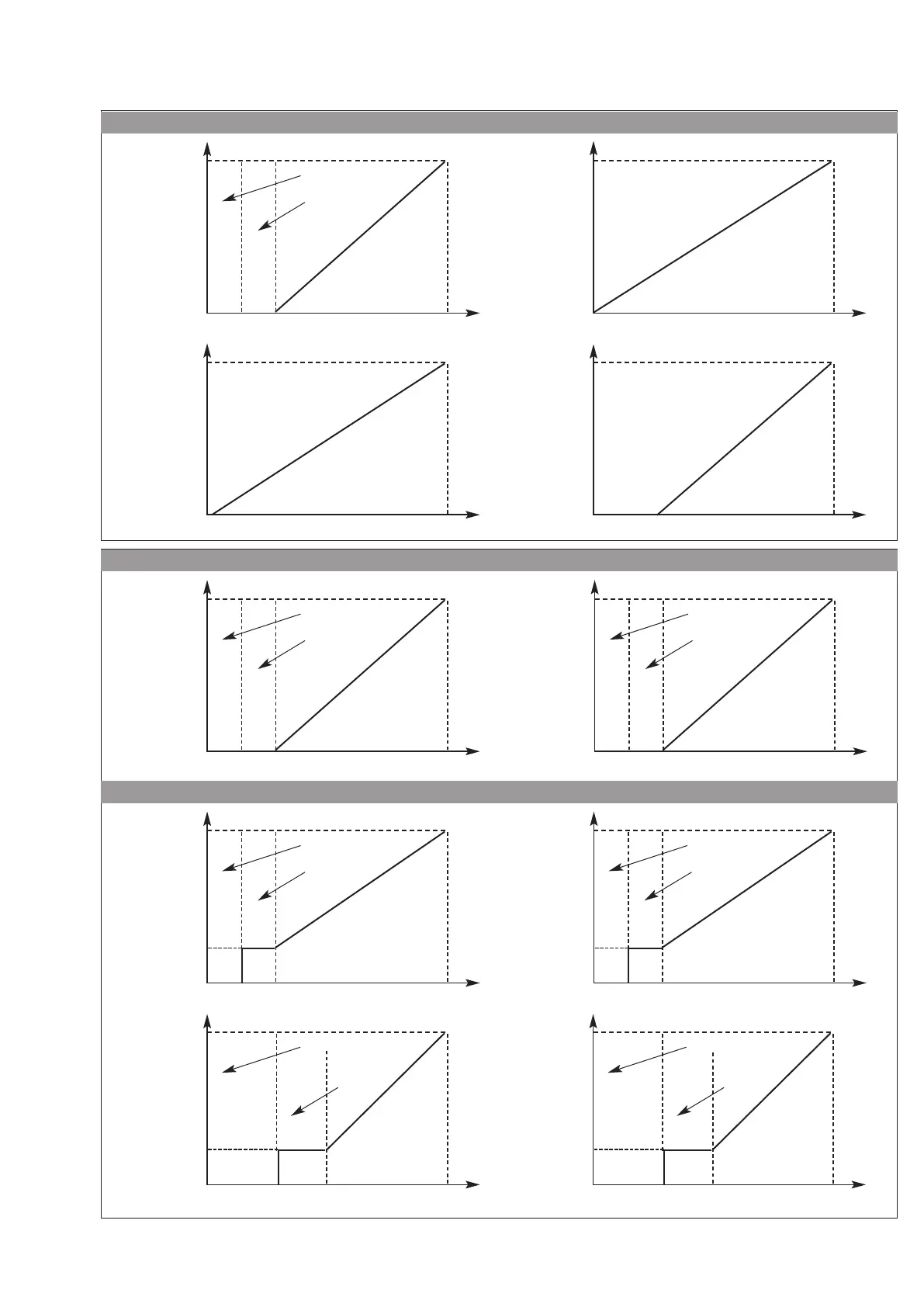
Control laws
IN1 : Input signal in « Constant pressure » and « P.I.D. control » mode
100%
Sensor signal 4-20mA
0 2 4
20
Input current (mA)
Value
in % of the range of
measurement of the
sensor
Between 0 and 2 mA, cable is
considered as broken
Safety
area
100%
Set value 4-20mA
0 2 4
20
Input current (mA)
Set value
in % of the range
of measurement of
the sensor
Area where converter stops
Safety
area
100%
Set value 0-10V
0 1 2
10
Input voltage (V)
Set value
in % of the range
of measurement of
the sensor
Area where converter stops
Safety
area
100%
Sensor signal 0-10V
0
10
Input voltage (V)
Value
in % of the range of
measurement of the
sensor
100%
Sensor signal 0-20mA
0 220
Input current (mA)
Value
in % of the range
of measurement of
the sensor
100%
Sensor signal 2-10V
0 10
Input voltage (V)
Value
in % of the range of
measurement of the
sensor
IN2 : Input of the external set value control in « Constant pressure » and « P.I.D. control » mode
IN2 : Input of external frequency control in « Speed control » mode
100%
~
30%
~
30%
External Signal 0-20mA
0 2 4
6 1
20
Input current (mA)
Frequency of
the converter
Area where converter stops
Safety
area
100%
External Signal 4-20mA
0
20
Input current (mA)
Frequency
of the converter
Area where converter stops
Safety
area
~
30%
3 5
100%
External Signal 2-10V
0
10
Input voltage (V)
Frequency
of the converter
Area where converter stops
Safety
area
100%
~
30%
External Signal 0-10V
0 1 2
10
Input voltage (V)
Frequency of
the converter
Area where converter stops
Safety
area
 Loading...