a. Measuring Directivity At 2 GHz and Above.
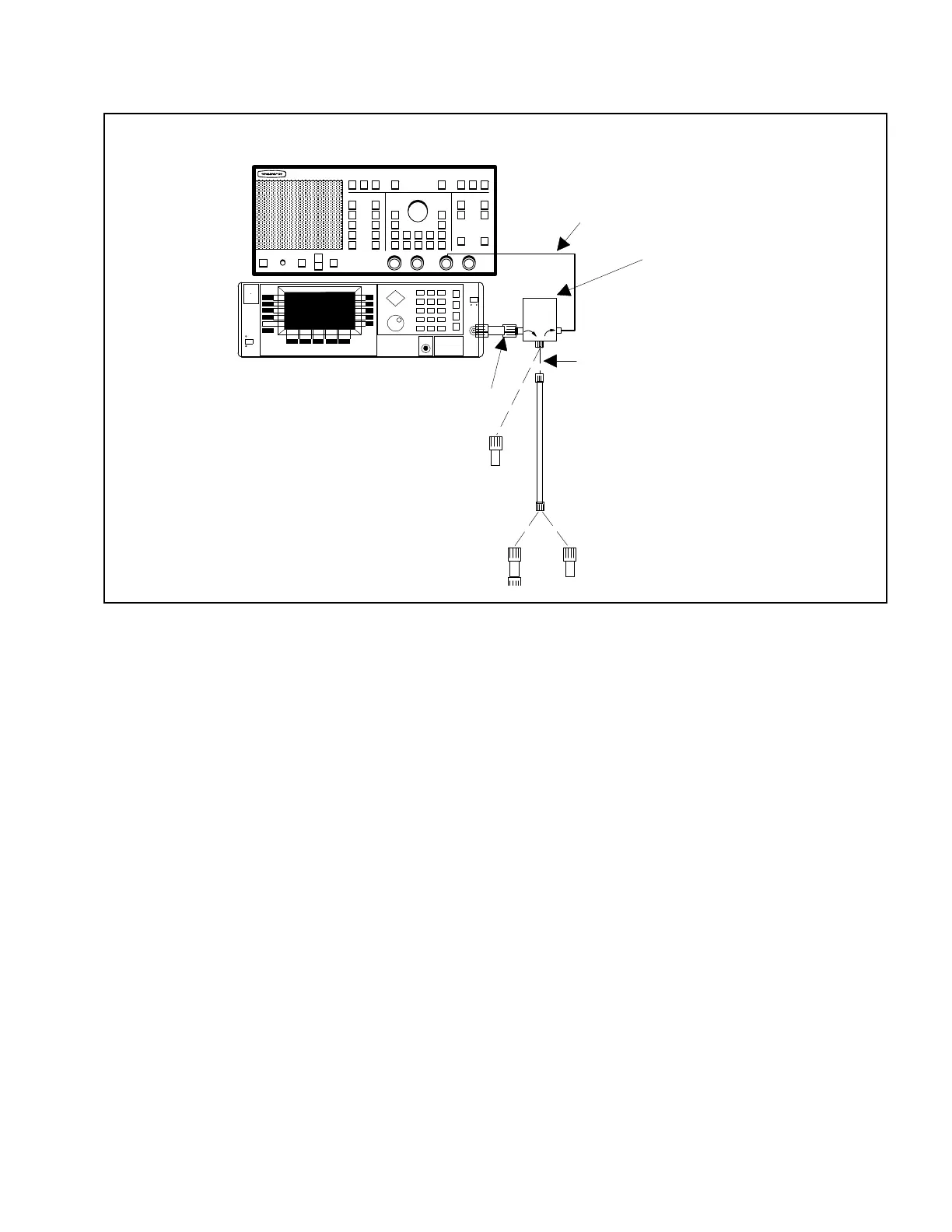
1. Connect test setup as shown in Figure 5.
2. Press LINE key on signal source to OPERATE.
3. Press POWER key on network analyzer to ON.
4. Press SYSTEM key on signal source, then se-
lect the Reset softkey, from the displayed
menu.
5. Set signal source for frequency range of de-
vice-under-test (DUT) and for maximum pos-
sible power, as described below.
(a) Press CW/SWEEP SELECT key.
(b) Select the Analog softkey from the dis-
played menu.
(c) Select the Edit F1 softkey from the dis-
played menu.
(d) Using the Cursor Control Key or Rotary
Data Knob, edit the F1 parameter to
equal the low-end frequency of the SWR
Autotester or Bridge under test.
(e) Select the Edit F2 softkey and repeat
step (d) for the high-end frequency.
(f) Select the Edit L1 softkey, and repeat
step (d) to display the source’s maximum
power level value.
6. Press SYSTEM FUNCTION MENU key on net-
work analyzer.
7. Using MENU up-down keys: Highlight RE-
SET, then press SELECT key.
8. Press CHANNEL 2 key to OFF.
9. Press GRATICULE ON/OFF key to ON.
10. Press CHANNEL 1 MENU key.
11. Using MENU up-down keys: Highlight RE-
TURN LOSS, then press SELECT key.
12. Press CALIBRATION key.
AIR LINE
OPEN/SHORT
34-SERIES
ADAPTER
562 SCALAR NETWORK ANALYZER
20 dB OFFSET
CONNECT DASHED LINE CONNECTIONS
WHEN DIRECTED BY PROCEDURE
SWR AUTOTESTER OR
BRIDGE UNDER TEST
(IF TESTING BRIDGE, USE 560-7 SERIES
DETECTOR INSTEAD OF 10 BX CABLE
560-10BX CABLE
REFERENCE TERMINATION
(<2 GHz MEASUREMENTS)
68147B SYNTHESIZED SWEEP GENERATOR
Figure 5. Test Equipment Setup for Directivity Measurement
SWR OMM 7
 Loading...