24. Using MENU up-down keys: Highlight
OFFSET dB, then press SELECT key.
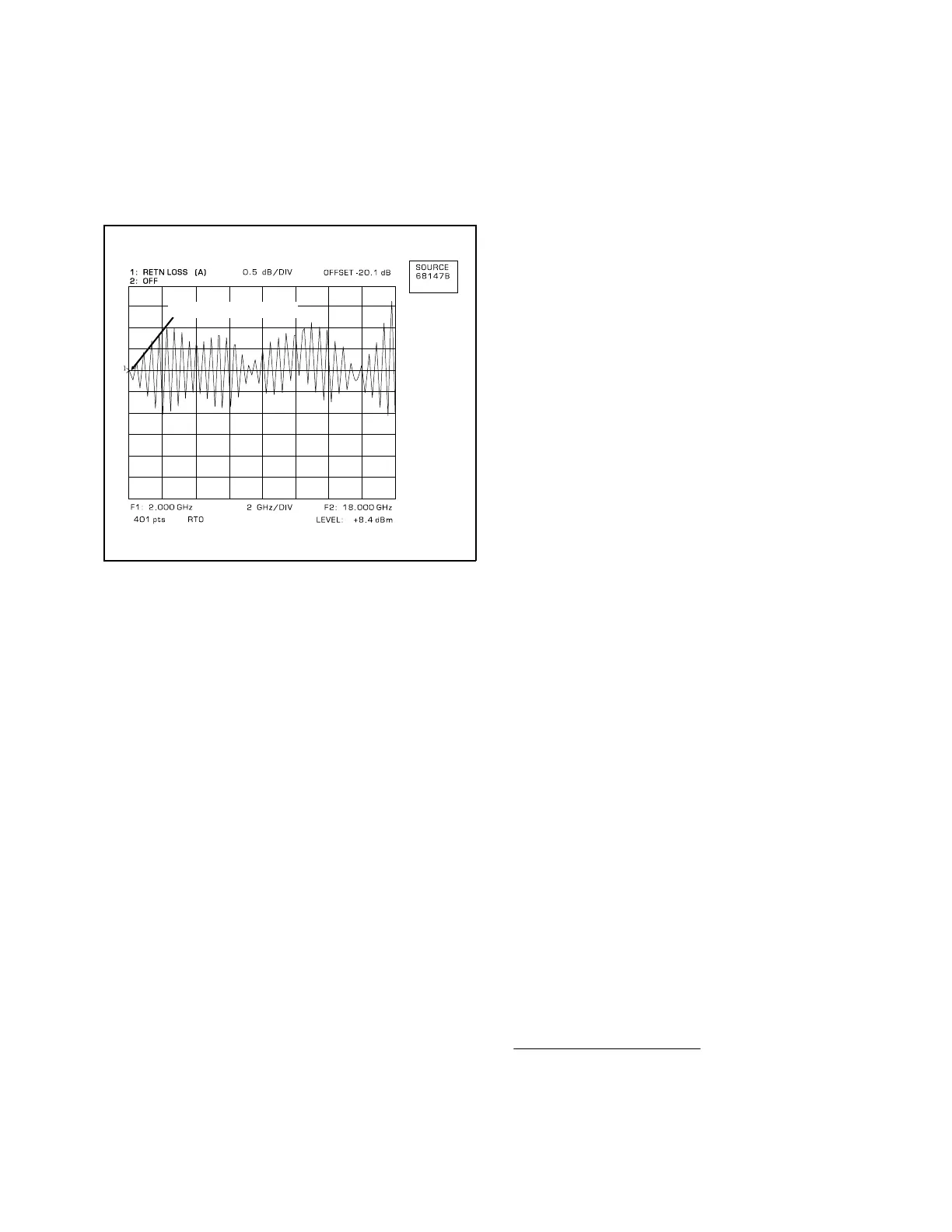
25. Using DATA ENTRY/CURSOR knob, align the
Channel 1 signal with the reference line (Fig-
ure 8).
26. Using MENU up-down keys: Highlight RESO-
LUTION dB/DIV, then press SELECT key.
27. Read OFFSET value from top of display.
This is the value of the 20 dB Offset.
28. Observing the displayed ripple pattern, select
the ripple with the greatest amplitude and
position its average point (see NOTE) on the
reference line.
NOTE
The average point is approximately
halfway between the peak and
trough values for ripples 3 dB or
less. For ripples greater than 3 dB,
refer to Table 6.
29. Measure the peak-to-peak value of the se-
lected ripple.
30.
In the “REF ±X, Peak to Peak Ripple, dB”
column of Table 6, find the value nearest to
the peak-to-peak signal value measured in
step 29.
31. Read the coordinate value from the “X dB
Below Reference” column.
32. Add the dB value from step 30 to the value
read in step 31. The sum is the worst-case
directivity of the SWR Autotester or bridge. It
should equal or exceed the specification in
Table 1 or 2.
b. Directivity Measurements Below 2 GHz.
1. Set up equipment as shown in Figure 5.
2. Perform steps 2 thru 13 of subparagraph a.
3. Connect termination to test port of SWR
Autotester or bridge being measured*.
4. Press CHANNEL 1 MENU key.
5. Using MENU up-down keys: Highlight REF
LINE, then press SELECT key.
6. Using DATA ENTRY knob, set reference line to
midscale.
7. Press CHANNEL 1 OFFSET/RESOLUTION
key.
8. Using MENU up-down keys: Highlight OFF-
SET dB, then press SELECT key.
9. Using DATA ENTRY knob, set OFFSET dB for
the directivity value of the SWR Autotester or
bridge being measured.
10. Using MENU up-down keys: Highlight RESO-
LUTION dB/DIV, then press SELECT key.
11. Using DATA ENTRY knob, set RESOLUTION
dB/DIV for a convenient value.
12. Observe analyzer display. If measured direc-
tivity signal is below the reference line, then
the directivity is within the specified value.
REFERENCE LINE
Figure 8. Signal Aligned With the Reference Line
* The return loss of the termination must be higher than the
directivity of the SWR Autotester or bridge being measured.
The WILTRON terminations recommended in Table 4 meet
this requirement.
SWR OMM 9
 Loading...