EasyManua.ls Logo

WiMo miniVNA PRO2 User Manual

WiMo miniVNA PRO2
4 pages
To Next Page IconTo Next Page
Page #1 background imageLoading...
Page #1 background image
Hardware Guide for miniVNA PRO2
+49 7276 / 96680
www.wimo.com info@wimo.com WiMo 2018
1
Congratulation ….
on your choice of miniRadioSolutions analyzer.
This is the hardware reference manual.
Safety
Please carefully read the safety instruction included in this manual.
The Software for miniVNA PRO2 is continuously developed. The current software is always downloadable from the internet.
For the latest software and updates, visit www.miniradiosolutions.com and http://vnaj.dl2sba.com/
The new miniVNA PRO2 is an extraordinary and unique hand-held vector network analyzer that makes available a multitude of new
features and capabilities which are perfect for checking antennas and RF circuits for hams and commercial users. Together with your
PC/Laptop, you can add to your laboratory the further advantages of having this first-class VNA instrument.
This is the first world’s wireless analyzer able of scanning and sending the data using an integrated Blue-tooth module to a remote
PC/Notebook up to 100 meters from the miniVNA PRO2’s location. This makes real-time antenna set-up easy!
Basic Carton Content
Hardware Guide
…………
……….
………….
Question and Answer IconNeed help?

Do you have a question about the WiMo miniVNA PRO2 and is the answer not in the manual?

WiMo miniVNA PRO2 Specifications

General IconGeneral
BrandWiMo
ModelminiVNA PRO2
CategoryMeasuring Instruments
LanguageEnglish

Summary

Safety Instructions

Hazardous Environments

Guidance on avoiding operation in hazardous areas and potential liability.

Care and Safety

Instructions for cleaning the unit and handling water exposure.

Li-ion Battery Operation

Regulations and precautions for battery disposal and handling.

User Information

Information on waste disposal and recycling of electrical equipment.

Connections

USB Connection

Details on using the USB port for power and PC communication, including driver installation.

Power-On and Bluetooth

Information on power supply, battery operation, and Bluetooth communication requirements.

Extension Port RJ45

Description of the RJ45 port for future product connections.

Reset Switch

Function of the reset switch for CPU and firmware upgrades.

RF Side Connections

DUT Port

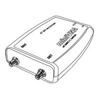
Details on connecting the antenna under test and voltage/power limits.

DET Port

Details on using the DET port for filters/amplifiers and voltage/power limits.

Battery Connection

Battery Connection Procedure

Step-by-step guide for connecting the battery pack to the PCB.

LED Indicators

LED Placement and Meaning

Explanation of the function and color of each LED indicator on the device.

Bluetooth Operation

BT Module Activation

Procedure for enabling the Bluetooth module and initiating pairing.

Optional Accessories

Suggested Option

Recommendation for a calibration kit with SMA termination.