Do you have a question about the Wincor Nixdorf BEETLE /iPOS plus and is the answer not in the manual?
Declares compliance with essential requirements of Directive 1999/5/EC, including multilingual statements.
Equipment complies with FCC limits for uncontrolled environments; maintain 20cm distance from radiator.
Complies with FCC Part 15 limits for Class A digital devices; provides protection against harmful interference in commercial environments.
Device complies with BSMI directive CNS13438 for electromagnetic compatibility, limits for Class B product.
iPOS plus meets ENERGY STAR version 6.0 eligibility criteria for computers; application for listing available.
Clean housing with dry, lint-free cloth; use plastic-surface cleaner if needed; disconnect power before cleaning.
Product designed with environmental consciousness; manufactured from reusable components; safe disposal of non-reusable parts assured.
Damages from improper maintenance, use, modifications, or location are not covered; wear and tear parts excluded.
Manufacturer not responsible for RFI/TVI from unauthorized changes; use approved cables/devices; authorized personnel for repairs.
Conforms to safety standards; avoid moisture condensation; use grounded power socket; disconnect power before any work.
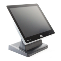
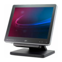
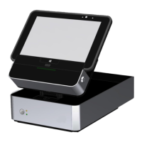
Identifies front panel components: Display, Stand, Brightness LEDs, Power status indicator, On/off button.
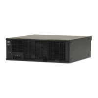
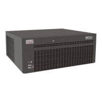
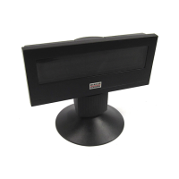
Identifies rear panel components: Stand, Base cover, Back cover, Frame cover, Peripheral connection covers, RAM/mini-PCIe cover.
Instructions on how to carefully remove the back cover of the stand to avoid damage.
Details the AC Power Adapter, including Power Connector, DC Power Out, and Power LED.
Describes front panel elements: Brightness buttons, Activity indicator (LEDs), Power status indicator, Power button.
Provides information for preparing the system for installation.
Steps to unpack, verify delivery contents against the note, and handle potential damage.
Device designed for in-house installation (desktop, pole, or wall-mounted); avoid extreme environmental conditions.
Guidelines for setting up the terminal workplace to avoid glare and ensure comfortable viewing.
Details the system's components including processor, RAM, storage, and display options.
CAUTION: Risk of explosion. Use identical batteries. Follow steps carefully and ensure system is off.
Steps to replace the RAM module: ensure system is off, remove cover, release catches, replace module.
Benefits include fast processing, high sensitivity, high resolution, improved legibility, and anti-glare.
Responds to light touches; single finger acts as left mouse button; two fingers for zoom/rotate.
Turn off system before cleaning. Use mild, abrasive-free glass cleaner; avoid acetic acid.
Constructed with hard-coated polyester top sheet over glass; touch accuracy unaffected by top sheet damage.
Touch acts like left mouse click; requires light pressure; stylus material recommended.
Turn off system. Clean with water-based solvent or non-abrasive cleaner; avoid acetic acid/methylene chloride.
Instructions for installing an optional antenna kit, including components and initial steps.
Instructions for installing an optional Wi-Fi flexible antenna kit, listing components and initial steps.
Drawings and specifications for desktop and wall mount versions in millimeters; views are not to scale.
Minimum clearance for ventilation and site preparation for wall mounting.
Ensures flat level area for desktop, avoids high-traffic for wall mount, checks ventilation and power access.
Instructions for attaching the monitor to its stand, requiring a Torx screwdriver.
Steps to lay the display down, tighten screws, remove cover, and connect cables for mounting.
Steps to connect all cables, ensuring snug fit and proper routing of power connector and ferrite core.
Steps to bring the display to the stand, hook screws, and connect power supply.
Steps to tilt the system, open the cover, and connect cables to assigned connectors.
Procedures for safely disconnecting various plug types (MINI-DIN, RJ12, USB-A).
Available media: 1x 2.5" drive bay for HDD or SSD; explanation of SSD.
Steps to replace HDD/SSD: ensure system off, tilt display, pull down cover, remove drive carrier.
Instructions to power on the system and access BIOS setup; OS boots if storage is present.
Perform orderly shutdown via OS; press/hold power button for unresponsive systems; wait after AC switch-off.
Error conditions reported by blinking red LED; decode by counting pulses and checking table.
Details processors, memory, display, touch options, audio, mass storage, expansion slots, TPM, RFID/NFC, and I/O.
Covers peripheral interfaces, side-attached options, supported OS, middleware, mounting, environment, IP rating, certifications, dimensions, weight.
Details AC Power Adapter and Port Extender specifications for desktop and standalone use.
Details total power availability and budget for system integrators to decide external device connections.
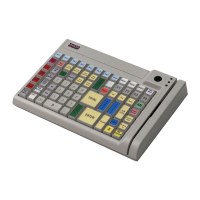
Lists approved printers for connection to the +24Vdc Powered USB port; warns against using unlisted printers.
Instructions for assembling the Wi-Fi antenna to the flap and the Wi-Fi module to the mini PCIe adapter.
Glossary of common abbreviations used in the manual, such as CE, ESD, HDD, LAN, etc.
| Display Size | 15 inches |
|---|---|
| Resolution | 1024 x 768 |
| RAM | 2GB or 4GB |
| Storage | SSD |
| Connectivity | Ethernet, USB |
| Touch Technology | Resistive |