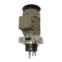
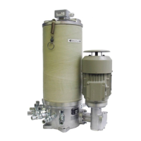
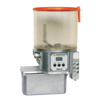
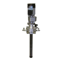
The WOERNER Gear-type pump unit, encompassing the GFZ, GFM, and GEZ series, is designed for the exclusive delivery of lubricating oils or lubricating greases in central lubrication systems. This operation manual, applicable to series versions from model year 2015, provides essential information for commissioning, operation, and maintenance, ensuring proper, efficient, and safe use.
Function Description:
The pump unit operates by absorbing lubricant through the suction hole of the gear pump. The interdigitating gears increase the lubricant's pressure, delivering it from the gear pump aggregate to the pressure line connection. GFZ series pump units are equipped with pressure relief valves, allowing for adjustment of the maximum pressure in the feed pipe. The pump unit is self-priming, generally eliminating the need for air removal during filling.
Important Technical Specifications:
The pump unit consists of three main components: a gear pump, a flange, and an electric motor. Technical details for specific models are provided in data sheets (chapter 11.5).
- Medium: Lube oils or lubricating greases.
- Viscosity:
- GFM-F, GFM-G: 100 ... 1350 cP
- GFM-N, GFM-L, GFM-L01: 16 ... 1350 cP
- GFZ-B, GFZ-C, GFZ-D: Mineral oil, 100 ... 1350 cP
- GFZ-N, GFZ-L, GFZ-L01: 16 ... 1350 cP
- GEZ-B, GEZ-C: 16 ... 1520 cP
- Medium Temperature:
- GFM-F, GFM-G, GFZ-B, GFZ-C, GFZ-D: -20 ... +80 °C
- GFM-N, GFM-L, GFM-L01, GFZ-N, GFZ-L, GFZ-L01: -15 ... +80 °C
- GEZ-B, GEZ-C: -20 ... +130 °C
- Ambient Temperature:
- GFM-F, GFM-G, GFZ-B, GFZ-C, GFZ-D: -20 ... +40 °C
- GFM-N, GFM-L, GFM-L01, GFZ-N, GFZ-L, GFZ-L01: -20 ... +40 °C
- GEZ-B, GEZ-C: -20 ... +50 °C
- General ambient temperature range: Lower limit -20 °C, Upper limit +40 °C.
- Permissible Negative Pressure: -0.3 bar for all models.
- Flow Rate: Varies by model and lubricant viscosity, operating pressure, and pump rotation. Examples include:
- GFZ-B, GFZ-C, GFZ-D: 0.06 ... 1.00 l/min
- GFZ-N: 0.8 ... 13.8 l/min
- GFZ-L, GFZ-L01: 2.8 ... 37.0 / 2.8 ... 38.3 l/min
- GFM-F, GFM-G: 0.06 ... 1.00 l/min
- GFM-N: 0.8 ... 13.8 l/min
- GFM-L, GFM-L01: 2.8 ... 37.0 / 2.8 ... 57.8 l/min
- GEZ-B, GEZ-C: 0.25 ... 1.0 l/min
- Sealing Material: NBR or FPM (FPM for GEZ-B, GEZ-C).
- Materials in Contact with Media: Al, St.
- Motor Type of Construction (DIN EN 60034-7): IM 3611, IM 3011, IM 2101, IM 2001.
- Flange (DIN EN 50347): FT 75, FT 85, FT 100, FT 130, FF 130, FT 73.
- Relative Humidity: Max. 70%.
- Noise Level: <70 dB(A).
- Suction Height: Maximum 800 mm.
- Suction Pipe Length: Maximum 1000 mm.
- Conformity: EC directive on machinery (2006/42/EC) and electromagnetic compatibility (2004/108/EC). ATEX compliance (2014/34/EU) for specific types, requiring operation within -20 to +40 °C, proper grounding, and avoidance of ignition sparks.
Usage Features:
- Conventional Usage: Exclusively for lubricating oils/greases in central lubrication systems, adhering to safety notes, maintenance instructions, and applicable regulations.
- Prohibited Usage: Delivery of gases, liquefied gases, vapours, highly inflammable/explosive media, or foodstuffs. Operation in aggressive atmospheres (solvent vapours, acids, lyes, salt water mist) is discouraged due to potential damage.
- Installation: Requires a suction pipe with adequate diameter and an angled opening. The pump unit is assembled to the top side of the lubricant reservoir, requiring a corresponding, stable, and even hole pattern. Bolted with 4 screws, with an optional flat seal between flange and reservoir.
- Power Supply: Connect the motor to the local energy supply, observing nominal voltage. Adequate protection is required. Electrical wiring must be performed by qualified electricians in accordance with DIN VDE 1000-10.
- Commissioning: The pump unit is factory-checked and ready for operation. Before starting, fill the reservoir with clean lubricant, ensuring the filling level is not lower than 10-15 mm above the reservoir's bottom edge. Avoid dry running. Lube point lines must be clean and unobstructed. If equipped with an adjustable pressure relief valve, open it before switching on the pump unit. Adjust the pressure relief valve to the desired operating pressure once lubricant emerges from the lubrication point pipes.
- Shutdown: The unit is shut down by switching off and disconnecting from the external power supply.
- Troubleshooting: A comprehensive table guides users through common faults (e.g., motor not starting, no pressure build-up) and their remedies, including checking power supply, lubricant, pressure control valve, and ambient temperature. Disconnecting the pump unit from the supply voltage is crucial before performing certain work.
Maintenance Features:
- Personnel Requirements: Servicing and repair work must be performed by technically skilled personnel with product-specific training, basic mechanical training, and professional experience. Electrical work must be done by skilled electricians in accordance with DIN VDE 1000-10.
- Safety Precautions: Always disconnect the unit from the power supply and secure it against restarting before cleaning, servicing, or repair. Prevent unauthorized access and keep foreign persons away from risk areas.
- Cleaning: Clean with commercially available cleaning agents, ensuring they do not attack pump unit materials. Do not use high-pressure cleaners or compressed air.
- Inspection Schedule:
- Daily: Check presence and functionality of safety facilities.
- Monthly: Check lube lines and connections for mechanical integrity and leakage.
- Weekly: Check pump units and components for mechanical integrity and leakage; check the filling level of the pump unit.
- Repair (Motor Exchange):
- Only use motors appropriate for pump units, referring to technical details and dimensions in the attachment.
- For GFM-F, GFM-G, GFZ-B to GFZ-D, GEZ-B, GEZ-C pumps: Involves plugging coupling element 1 onto the gear pump shaft, then the drive plate onto coupling element 1. Measure the distance between the drive plate and motor fixing points (a). Adjust coupling element 2 (mounted on motor shaft) to b = a-0.5 mm and fix it. Screw the motor to the flange, ensuring coupling element 2 studs interdigitate with the drive plate. Connect the motor to power supply.
- For GFZ-N, GFZ-L, GFZ-L01, GFM-N, GFM-L, GFM-L01, PFZ-N, PFZ-L, PFZ-L01, PFM-N, PFM-L, PFM-L01: These are supplied without motor but with connection flange. An elastic coupling is needed for motor connection. Ensure individual components of the elastic coupling (hubs and sleeves) have the same size. The procedure involves plugging the pump-suitable hub onto the gear pump shaft, then the sleeve onto the hub. Measure the distance between the hub and motor fixing points (a). Adjust the motor-mounted hub to b = a-4 mm and fix it. Screw the motor to the flange. Connect the motor to power supply.
- Accessories: Pressure relief valves are available for GFM-F to GFM-G pumps (Order-no. 940.221-65 to 940.229-65 for pressures 2.5 to 60 bar) and GEZ-B to GEZ-C pumps (Order-no. HDV-A/E/6 to HDV-A/E/45 for pressures 6 to 45 bar). When selecting, consider the maximum delivery pressure of the gear pump.
- Return Shipment to Factory: For repairs or disposal, a "Document of compliance" form must be fully completed and attached to the freight documents. The product must be discharged, clean, all openings closed, and packed safely. A detailed complaint description is required for damage assessment.