© 2004 Wohler Technologies Inc. ALL rights reserved
14
AMP2-DA/AVU and AMP2-DA/APP User Manual P/N 821584 Rev-A
E
Rear Panel Features
Section 2: Operation
(Continued)
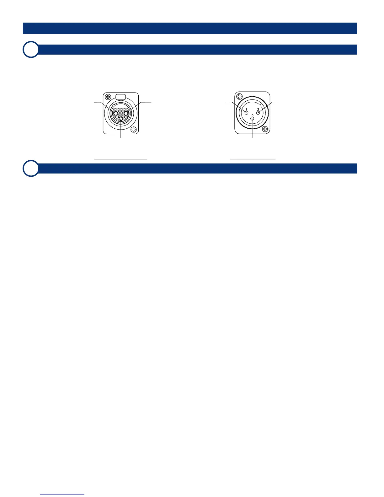
Selected Analog Output Connectors
These two 3-pin male XLR connectors are analog outputs of the selected source as assigned to the left and right speakers.
The left connector outputs the left channel (Channel A) and the right outputs the right channel (Channel B). Both connectors
are configured for low impedance connections and the output signals are not affected by the volume/balance controls or
headphone mute. For XLR pinout information see the diagram below.
Analog Input Connectors (LEFT [A] and RIGHT [B])
These two 3-pin female XLR connectors (Left and Right) accept standard analog audio signals and are configured for
balanced 70K Ω connections. For XLR connector pin-out information, see the diagram under Item E. Note that the analog
inputs are monitored only when the Analog/Digital Source Select Switch (Item 3, page 8) is set to ANALOG.
F
High (+)
Low (-)
Gnd
(Shield)
Pin-1 Pin-2
Pin-3
Pin-1
Gnd
(Shield)
Pin-2
High (+)
Pin-3
Low (-)
Female XLR Pinout Male XLR Pinout
 Loading...