Operation 13
MAN0476 (Rev. 2/10/2006)
DRIVELINE TO TRACTOR CONNECTION
To Install:
Pull locking collar back and at the same time push driv-
eline onto tractor PTO shaft until locking device
engages.
To Remove:
Hold driveline into position, pull locking collar back, and
slide driveline off tractor PTO shaft.
Figure 2. Lock Collar - Pull Back
SHREDDING MATERIAL
For shredding, set the cutter’s rear lower. Determine
how much lower to set the rear by experimenting in dif-
ferent situations.
CUTTING HEIGHT ADJUSTMENT
Keep all persons away from operator control
area while performing adjustments, service, or
maintenance.
■ Avoid low cutting heights. Striking the ground
with blades produces one of the most damaging
shock loads a cutter can encounter. Allowing
blades to contact ground repeatedly will cause
damage to cutter and drive.
1. Level cutter from side to side. Check by measuring
from cutter frame to the ground at each deck rail.
2. Adjust, using tractor 3-point arm leveling device.
NOTE: Keep the front of cutter slightly lower than
rear for best mowing.
3. Control cutting height with tractor 3-point arms,
rear tailwheel adjustment, or optional check chains.
4. To raise rear of cutter, move tailwheel arm down.
5. To raise front of cutter, raise tractor 3-point arms or
shorten optional check chains.
The cutting height is the distance between the blade
and the ground. The blades are approximately 8.5"
below the deck. To check cutting height, do the follow-
ing:
a) Place a straight edge along top edge of deck.
b) Select a cutting height; as an example, for an
approximate cutting height of 3", set the center of
the deck 11.5" above the ground:
c) Adjust the front-to-rear attitude from 1/2" to 3/4"
higher than the front.
TOP LINK ADJUSTMENT
IMPORTANT
■ When cutter is adjusted to transport position,
set upper stop on tractor lift quadrant to prevent
cutter from contacting the driveline when being
raised.
■ Select a top link mounting pin (maximum
length 3-5/8") that will allow floating link to swing
freely through the cutter A-frame bars.
1. Attach tractor top link (1) to lowest hole provided in
the tractor’s top link bracket (6).
2. Attach rear portion of tractor top link to the cutter
floating link (3). Select a top link mounting pin that
will allow the floating link to swing freely through
the cutter A-frame bars (5).
3. Raise cutter to transport position and adjust tractor
top link until cutter is level in the raised position.
NOTE: If you cannot level the cutter using the low-
est hole in the tractor’s top link bracket, move top
link to the next hole and level the cutter.
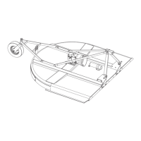
Figure 3. Top Link Adjustment
3" Desired cutting height
+ 5.88" Distance blade cutting edge is below deck
= 8.88"
1. Tractor top link
2. Cutter top link mounting pin
3. Floating link / clevis
4. Cutter hitch pin
5. A-Frame bar
6. Tractor top link bracket
 Loading...