26 Assembly
MAN0476 (Rev. 2/10/2006)
ASSEMBLY
DEALER SET-UP INSTRUCTIONS
Assembly of this cutter is the responsibility of the
Woods dealer. It should be delivered to the owner com-
pletely assembled, lubricated, and adjusted for normal
cutting conditions.
The cutter is shipped partially assembled. Assembly will
be easier if aligned and loosely assembled before tight-
ening hardware. Recommended torque values for hard-
ware are located in the Bolt Torque Chart, page 39.
Complete Dealer Check Lists, page 30 when you have
completed the assembly.
Full chain, rubber, or steel band shielding,
designed to reduce the possibility of thrown
objects, must be installed when operating in popu-
lated areas or other areas where thrown objects
could injure people or damage property. If this
machine is not equipped with full chain, rubber, or
steel band shielding, operation must be stopped
when anyone comes within several hundred feet.
Make sure spring-activated locking pin or collar
slides freely and is seated firmly in tractor PTO
spline groove.
Operate tractor PTO at the rpm speed stated in
“Specifications” section.
Always wear relatively tight and belted clothing
to avoid getting caught in moving parts. Wear
sturdy, rough-soled work shoes and protective
equipment for eyes, hair, hands, hearing, and head;
and respirator or filter mask where appropriate.
ASSEMBLE CUTTER
Disassemble Shipping Unit
1. Loosen mounting hitch pins.
2. Remove all parts that are wired and strapped to
cutter.
3. Remove tailwheel bracket, lift arms and height
adjustment bracket from cutter. Keep all hardware
for use in assembly.
4. Remove all hardware from manual tube.
Install A-Frame to Lift Arms
1. Loosen mounting pin (7) and swing A-frame arms
to an upright position.
2. Loosen and remove M20 cap screw (5) and lock
nut (6).
3. Place lift arm (2) on the outside of A-frame arm (1),
slide M20 cap screw (5) through lift arm (2), A-
frame arm (1), sleeve (4), clevis (3), A-frame arm
(1) and lift arm (2). Secure with M20 lock nut (6)
and tighten.
4. Tighten mounting pin (7) Torque to 475 lbs-ft.
5. Tighten hardware at other end of lift arms.
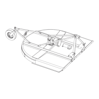
Figure 21. Lift Arms to A-Frame Connection
CD6827
5
6
7
1
1
2
2
3
4
1. A-frame arm
2. Lift arm
3. Clevis
4. Sleeve
5. M20 x 1.5 x 140 Cap screw
6. M20 Lock nut
7. Mounting pin (Cat 1)