22 Dealer Service
20944 (Rev. 2/3/2006)
DEALER SERVICE
The information in this section is written for dealer ser-
vice personnel. The repairs described require special
skills and tools. If your shop is not properly equipped or
your mechanics are not properly trained in this type of
repair, you may be time and money ahead to replace
complete assemblies.
Before servicing, adjusting, repairing or unplug-
ging, stop tractor engine, place all controls in neu-
tral, set park brake, remove ignition key, and wait
for all moving parts to stop.
Keep all persons away from operator control
area while performing adjustments, service, or
maintenance.
Make certain all movement of equipment com-
ponents has stopped before approaching for ser-
vice.
Always wear relatively tight and belted clothing
to avoid getting caught in moving parts. Wear
sturdy, rough-soled work shoes and protective
equipment for eyes, hair, hands, hearing, and head;
and respirator or filter mask where appropriate.
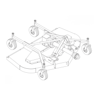
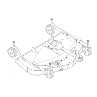
BLOCKING METHODS
Jack stands, with a load rating of 1,000 pounds or
more, are the only approved blocking device for this
mower. A minimum of four jack stands, located under
the mower as shown in Figure 14, must be installed
before working underneath this unit. Do not position
jack stands under wheels, axles, or wheel supports
because these components can rotate.
Do not work underneath unless it is properly attached
to tractor (see Operation Section), the brakes set, key
removed, and the mower blocked securely. The
mounted unit will be anchored to minimize side to side
and front to rear movement. The pull-type unit will be
anchored front to rear.
For the mounted unit, tighten tractor lower 3-point arm
anti-sway mechanisms to prevent side to side move-
ment.
For the pull-type unit, raise mower with the standard
ratchet adjustment link or the optional hydraulic cylin-
der. When the optional hydraulic cylinder is installed
the standard equipment transport bar must be pinned
in the raised position. With either the ratchet adjust-
ment link or the optional hydraulic cylinder, lower the
mower to transfer its weight to the jack stands, but do
not raise the rear wheels off of the ground.
When blocking, you must consider overall stability of
the unit. Just placing jack stands under the unit will not
ensure your safety. The working surface must be level
and solid to support the weight on the jacks stands.
Ensure jack stands are stable both top and bottom, and
mower is approximately level. With full mower weight
lowered on jack stands, test blocking stability before
working underneath mower.
Figure 14. Jack Stand Placement
(Tractor and Connection Not Shown)
BLADE SPINDLE
Blade Spindle Repair Tips
As a reference point, the grease fitting is in the top por-
tion of the spindle housing.
To minimize wear, the bearing cups, cones and sleeves
are press fit to the shaft and will require a press or sim-
ilar device for removal.
When disassembling, support housing casting to pre-
vent damage.
Remove bearing cups by placing a punch in housing
slots and driving cup out. Alternate punch positions
from side to side. Use care to prevent housing dam-
age.
Permatex 3-D Aviation Form-A-Gasket
®
or equivalent
is recommended as a sealant for spindle repair.
Blade Spindle Removal
Remove belt. Remove blades from spindle. Remove
bolt and washer from top of spindle shaft.
Remove split taper bushing (located on top of pulley)
by removing the two bolts and inserting them into the
threaded holes in bushing flange. Tighten alternately to
remove split taper bushing.
AWARNING
ACAUTION
 Loading...