Assembly 33
20944 (Rev. 2/3/2006)
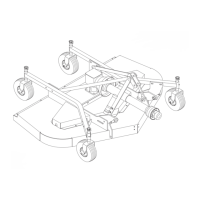
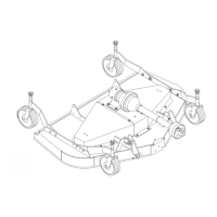
Figure 28. RM990-3 Hitch Installation
RM990-3 HITCH INSTALLATION
(Figure 28)
The RM990-3 is shipped with Category 1 hitch pins in
the shipping location. Remove bolt (1) and hitch pin
bracket (4). Remove the hitch pin (6) from the shipping
location and place it in the end hole. Insert the hitch pin
bracket (4) into the mast plate as shown. Slide sleeve
(3) through holes flush with outside of mast plate and
secure with bolt (1), washers (2), and hex lock nut.
Repeat for other side.
Remove bolt (8) and assemble 3-point brace bars (9)
on outside of A-frame bars (5). Re-install bolt (8)
through bars, spacer and top-link clevis (11).
Tighten all hitch assembly hardware. (See torque chart
in Operator’s Manual.)
Install PTO hanger bracket (13) to upper mast assem-
bly. Secure with flange lock nut (12). Do not over-
tighten lock nut. PTO hanger bracket should be able to
rotate freely out of the way when the mower is in oper-
ation.
1. 5/8 x 3-1/2" Bolt
2. 5/8" Flat washer
3. .64 x 1.00 x 2.09" Sleeve
4. Hitch pin bracket
5. A-frame bar
6. Category 1 mounting pin
7. 5/8" Hex nut
8. 1/2 x 6" Bolt
9. 3-Point brace bar
10. 1/2 Schedule 40 x 2-3/4" pipe
11. Top link clevis
12. 1/2" Flanged hex lock nut
13. PTO Hanger bracket