46 Assembly
MAN0943 (11/1/2013)
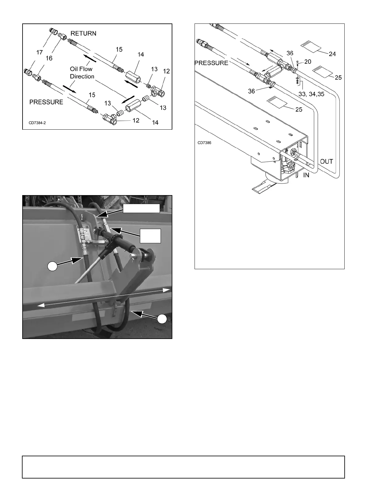
Figure 60. Hose Assembly
6. Route hose (11) from the IN side of the motor
between shredder and rockshaft and attach it to
tee (12) on the left side of the center plate.
7. Route hose (11) from the OUT side of the motor
between shredder and rockshaft and attach it to
tee (12) on the right side of the center plate.
Figure 61. Hose Routing
Install Hose Clamps
1. Place hose clamps (36) around hoses (11) and
center hoses between center plate.
2. Mark clamp holes in desired location on shredder
body and drill two 11/32" holes.
3. Secure hose clamps to shredder using 5/16 NF x
1-1/4 cap screws (20), flat washers (33), lock
washers (34) and hex nuts (35). See Figure 62.
Figure 62. Hose Clamp Installation
Connect Hoses to Tractor
NOTICE
■
Oil flow to hydraulic motor must not exceed 28
gpm.
1. Connect PRESSURE hose to a tractor rear remote
quick coupler that has a lever (handle) that can be
placed in the detent or locked position.
2. RETURN hose must be connected directly to the
tractor reservoir or to a specifically designated
motor return or ‘zero’ back pressure port.
Install Decals
Apply safety decals (24 & 25) to a clean surface on the
back of the shredder where they can be seen without
obstructions. Install decals (25) on either side of the
hose assembly. See Figure 62.
Check
Valve
11
Center Plate
RETURN
PRESSURE
L
e
f
t
R
ig
h
t
DP2
11
IN
OUT
20. 66 5/16 NF x 1-1/2 HHCS GR5
24.50530315 Decal, Hydraulic Pressure
25.50530263 Decal, Rotating Blades
33. 4378 5/16 Flat Washer
34. 2472 5/16 Lockwasher
35. 5283 5/16 NF Hex Nut
36. 1004695 Clamp, 1.94 Dia pipe