Assembly 45
MAN0943 (11/1/2013)
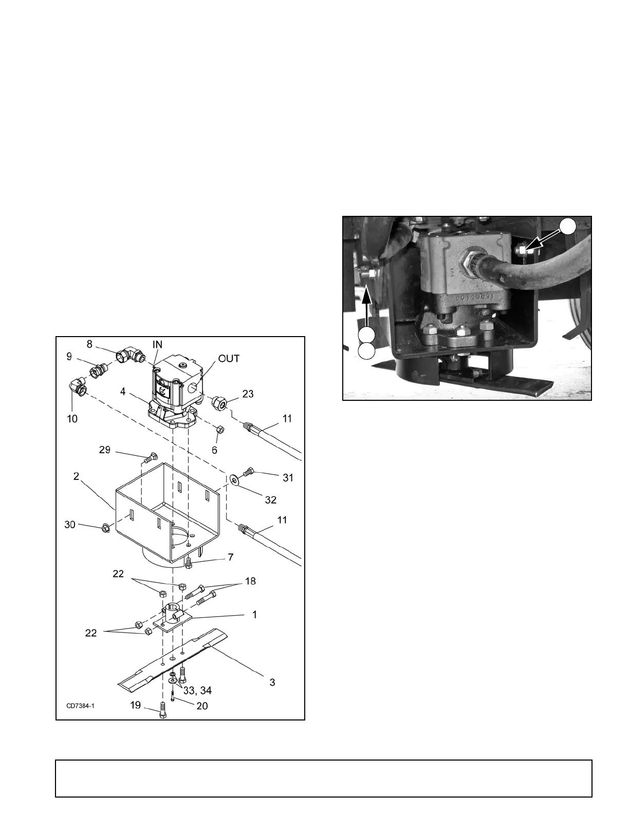
Assemble Motor and Blade - Figure 58
1. Install elbow (8), adapter (9), elbow (10) and hose
(11) to the IN or PRESSURE side of the hydraulic
motor.
2. Install adapter (23) and hose (11) to the OUT or
RETURN side of the motor.
3. Place motor (4) inside motor housing (2) and
secure using six 9/16 NC x 1-1/2 cap screws (7)
lock nuts (6).
Make sure OUT or RETRUN side of motor is on the
open side of the motor housing. Torque hardware
to 171 lbs-ft.
4. Slide blade hub (1) over motor shaft, install 1/4"
key and secure using one 5/16 NF x 1-1/2 cap
screw (20), flat washers (33) and lock washer (34)
in the bottom of the shaft. Torque to 19 lbs-ft.
5. Clamp hub to shaft using two 3/8 NC x 1-3/4 cap
screws (18) and lock nuts (22). Torque to 35 lbs-ft.
6. Secure blade (3) to blade hub using two 3/8 NC x
1-1/4 cap screws (19) and flange lock nuts (22).
Torque to 35 lbs-ft.
Figure 58. Motor Assembly
Install Motor Housing - Figure 59
1. Slide motor assembly between shredder center
channel and secure to the left side using two 1/2
NC x 1-1/4 carriage bolts (29) and flange lock nuts
(30).
2. Install 1/2 NC x 1 cap screw (31) and flat washer
(32) to the right rear hole of the motor housing and
secure with flange lock nuts (30).
3. Install 1/2 NC x 1-1/4 carriage bolt (29) and flange
lock nut (30) into the right front hole.
4. Raise motor housing to the bottom of the mounting
slots and torque hardware to 85 lbs-ft.
Figure 59. Motor Assembly Installed
Assemble Hoses
1. Attach male quick coupler (17) and adapter (16) to
the end of hose (15). Attach tee (12) to the
opposite end of hose.
2. Attach male quick coupler (17) and adapter (16) to
the end of second hose (15). Attach check valve
(14), nipple (13) and tee (12) to the opposite end of
hose.
NOTE: Make sure flow indicator arrow on the side
of the check valve (14) is pointing in the correct
direction. See Figure 60
3. Install check valve (14) and two nipples (13)
between the two tees (12).
NOTE: Make sure flow indicator arrow on the side
of the check valve (14) is pointing in the correct
direction.
4. Place hose assembly around center plate of
shredder and drape quick couplers over the front of
the shredder. See Figure 60 and Figure 61.
5. Make sure hose with check valve is on the right
side of the center plate.