C
Clayton JonesAug 2, 2025
Why does the Woodward 9907-252 engine speed decrease with load increase?
- Jjennifer46Aug 2, 2025
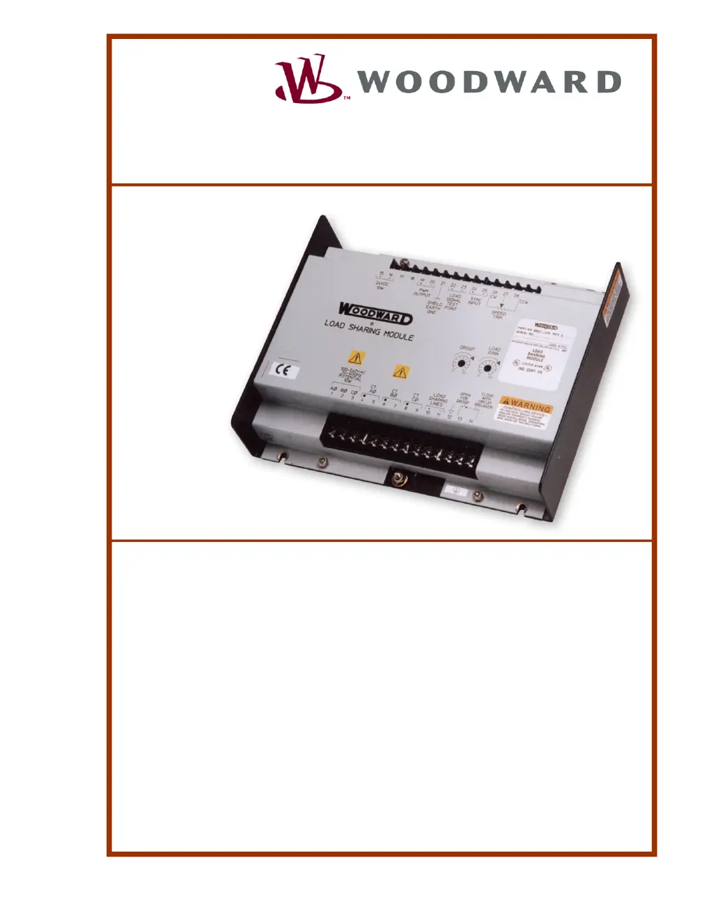
An undesirable speed decrease with load increase in your Woodward Control Unit can occur due to several reasons: * The droop mode switch or auxiliary contact might be open, or the Load Sharing Module might be in droop mode. To resolve this, jumper Load Sharing Module terminals 13 and 14. If this corrects the problem, replace the wiring or switch as required. The module will not enter droop mode with the terminals connected. * There may be improper engine operation. Operate the engine and observe the speed while applying a load. * A faulty engine control could be the cause. To check this, disconnect the Load Sharing Module and load the engine as a single, isolated unit.