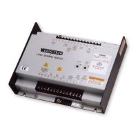
Manual 02035 Load Sharing Module
Woodward 19
Chapter 4.
Theory of Operation
Introduction
This chapter describes the operation of the Load Sharing Module and its internal
circuits. Figure 1-3 is a block diagram of the circuits in the module.
The Load Sharing Module senses the power output of a generator and provides
a 0.5–4.5 Vdc signal to the speed control to adjust the power output of the
engine-generator set to match the reference power level. The Load Sharing
Module can also produce a droop condition (instead of isochronous load-
sharing), making it possible to connect the generator set in parallel with either a
generator set which is running isochronously, or with an infinite bus.
Power Supply
The internal power supply generates a regulated dc voltage for the operation of
the circuits in the Load Sharing Module. The power supply gets its power from
the engine 24 Vdc power source. To prevent damage to the unit that uses an
alternator or battery charging device, make sure the charging device is turned off
before disconnecting or connecting the 24 Vdc supply to the unit.
Power Sensor
Generator load is measured by the power-sensor circuit of the Load Sharing
Module. The power-sensor circuit senses current amplitude, and produces a load
signal proportional to the current amplitude times the power factor. The potential
input comes from potential transformers (PTs) and the current input comes from
the current transformers (CTs). The circuit uses these two inputs to generate a
load signal which is then filtered and sent to the controller circuit. The load signal
voltage of each generator set will be proportional to the percentage of rated load
on the generator set.
Ammeters and voltmeters may be driven with the same PT and CT wires.
Load Comparator Circuit
In the load comparator circuit, the load signal voltage is balanced with the other
generator sets in the system via the load sharing lines. The comparator circuit of each
Load Sharing Module includes a load gain potentiometer to adjust each generator set's
load signal so that the load signal voltage of each is the same at full load. This
compensates for varying CT ratios or different generator set sizes. The load sharing
voltage will be one-half the measured voltage of the load signal test point.
Speed Trim Circuit
A speed-trim potentiometer can be added to the Load Sharing Module to permit
remote adjustment of the load or frequency of the generator. The speed trim is
normally used for manual synchronization of a generator set with an existing bus
or to change the load demand when in droop mode.

 Loading...


