REAR
FLUE
ASSEMB
LY
Measure
and
cut
the
air
and
flue ducts to length. Always check
the
dimensions before cutting. Measure the equivalent wa
ll
thick-
ness W
frof
the
inounting wall
to
the external wall. See Fig12.
Air
duct length = W + 65mm. Cut the air duct to length leaving
the
cut
square and smooth.
Do
not
cut
the
drilled
end
of
the
air
duct assembl
y.
Flue duct length = W + 1 OSmm.
Cu
t the flue duct to length.
Assemble the air and flue ducts and the terminal assembly.
Do
not
forget to
fit
the internal support spider to
an
extended
flue
system.
See F
ig.
14.
join
any
extended air ducts together applying a thin smear of
sili-
cone
sealant
around
the
end
of
the
penetrating
duct
before
pushing fully home into
the
expanded end of
the
other duct. See
Fig.
14.
Dri
ll
through the guide hol
es
using the
3mm
drill supplied
and
fix
the
ducts
an
d
the
terminal
assembly
us
ing
the
self-tapping
screws provided.
From outside, ease
the
complete assembly through the hole in
the
wall. The air duct fits more easily
if
it
is
lubricated with soap solu-
tion. Fully engage the air duct into the air du
ct
clamp assembly
an
d tighten
the
three screws. Make sure
that
the
silicone seal
is
not
distorted when entering
the
air duct.
REAR
FLUE
CONNECTION
Pull
the
inner flue duct forward to p
ro
trude SOmm into the inner
casing.
Do
not
exceed this figure. Slide
the
flue duct clamp over
the fan
out
let.
Rep
lace
the
fan
assemb
ly ensuring
that
the
flue
du
ct enters
th
e fan outlet to a depth of 20mm.
Ro
tate the flue duct clamp around until
the
screw
head
is
acces-
sible
an
d tighten.
Push
the
fan fully
home
and
tighten
the
fan
fixing screw. See
Fig
. 1 8.
Make good
the
external brickwork
or
rendering. The inside edge
of
the
rolled chann
el
on
the
terminal assembly
will
be
1
Om
m from
the
wall face.
Rec
onn
ect
th
e electricity
su
pply plug and suction tubes to the fan.
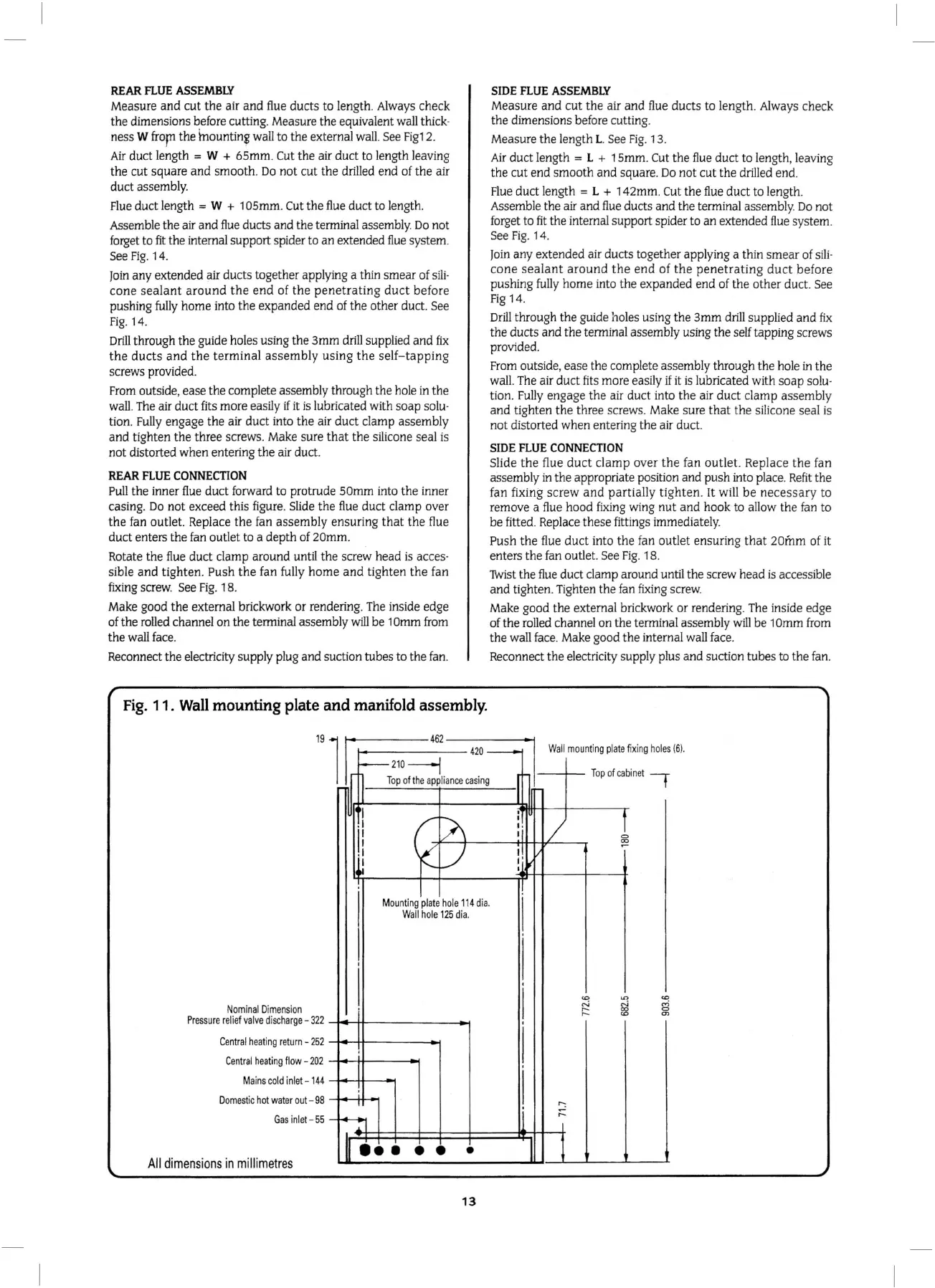
Fig.
11.
Wall
mounting
plate
and
manifold assembly.
19
462
SIDE
F
LUE
ASSEMBL
Y
Measure
and
cut
the
air
and
flue ducts
to
length. Always check
the dimensions
be
fore cutting.
Measure the leng
th
L.
Se
e
Fig.
13.
Air
duct length = L + 1 Smm. Cut
the
flue duct to
le
n
gt
h, leaving
the cut end
smooth
and
square.
Do
not
cut
the drilled end.
Flue duct length
= L + 142mm. Cut
the
flue duct to length.
Assemble the a
ir
and
flue
ducts
and
the terminal assembl
y.
Do
not
forg
et to
fit
the internal support spider to
an
extended flue system.
See
Fig
.
14
.
jo
in any extended air ducts together applying a thin
smear
of
sili
-
cone
sealant
around
the
end
of
the
penetr
ating
duct
before
push
i
ng
full
y home into the ex
pan
ded
end
of t
he
othe
r duct. See
Fig
14.
Dr
ill
throu
gh
the guide holes using
the
3mm
drill s
up
plied
an
d
fix
the
duc
ts
and
t
he
terminal assembly using the self
ta
pping screws
provided.
From
ou
tside, ease the complete assembly through the hole in the
wall. The air duct fits more eas
ily
if
it is lubricat
ed
wi
th
soap
solu-
tion.
Fu
ll
y engage
the
air duct into
the
air duct clamp
as
sembly
and
tighten
th
e three screws. Make sure
tha
t
the
silicone seal
is
not distorted when entering
th
e air duct.
S
IDE
F
LUE
CONNEC
TION
Slide t
he
flue
duct
clamp over
the
fan outlet. Repl
ace
the
fa
n
assembly in the appropriate position and push into place.
Refit
the
fan
fi
xing
screw
and
partia
ll
y
tighten
. It will
be
necessary
to
remove a flue hood fixing wing
nut
and
hook to a
ll
ow
the fan to
be
fitted.
Rep
lace these fittings immediately.
Push the flue
duct
into t
he
fa
n outlet
ensur
ing t
hat
20inm
of it
enters the fan outlet. See
Fig.
1 8.
1Wist
th
e flue duct clamp around until the screw head is accessible
and
tighten.
Ti
ghten
the
fan
fix
ing screw.
Make good
the
external brickwork
or
renderin
g.
The inside edge
of the ro
ll
ed
c
hann
el
on
the terminal assembly
will
be
1
Omm
from
the wall face. Make good the internal wa
ll
face.
Reconnect the electricity supply plus
an
d suction
tub
es
to
the
fan.
l
420-
Wall
mount
i
ng
pla
te
fix
i
ng
ho
l
es
(6)
.
Nom
inal
Di
mens
ion
Pr
ess
ure
relief
valve
di
scharge-
322
Central
h
ea
ti
ng
r
etu
rn-
252
Centra
l h
eating
fl
ow
-
20
2
M
ains
co
ld in
l
et
-
144
D
omestic
hot
w
ater
out
- 98
Gas
i
nle
t-
55
All
dime
ns
ions
in
millimetres
-
-
210
----1
l
Top
of
the
a
pP.
Ii
an
ce
casing
I
c
/\
.I
ll
_)
~~
1'-
I
Mo
unt
in
g
pla
te
ho
le 11
4d
ia.
Wall
hole
125
d
ia.
I
I
j
I
l
I
!
[-;!
.
•••
• •
•
13
r
Topofc
ab
in
et I
I
I
1
I
!i /
il
~
I'
I
I
I
'
I
<0
"'
<0
,...;
,...;
co;
,_
~
~
,_
'
I
I
r-:
;::
II
l