12. Instructions to the User
12.1 Instruct the user in the efficient and safe operation of
the
appliance and hand over the User's Instructions pamphlet.
12.2
Describe the operation and function of the control
s.
12
.3
Tell
the user of
the
action necessary
in
the event of
the
cen-
tral heating system not being used during frost conditions.
12.4
Tell
the user the sealed system pressure.
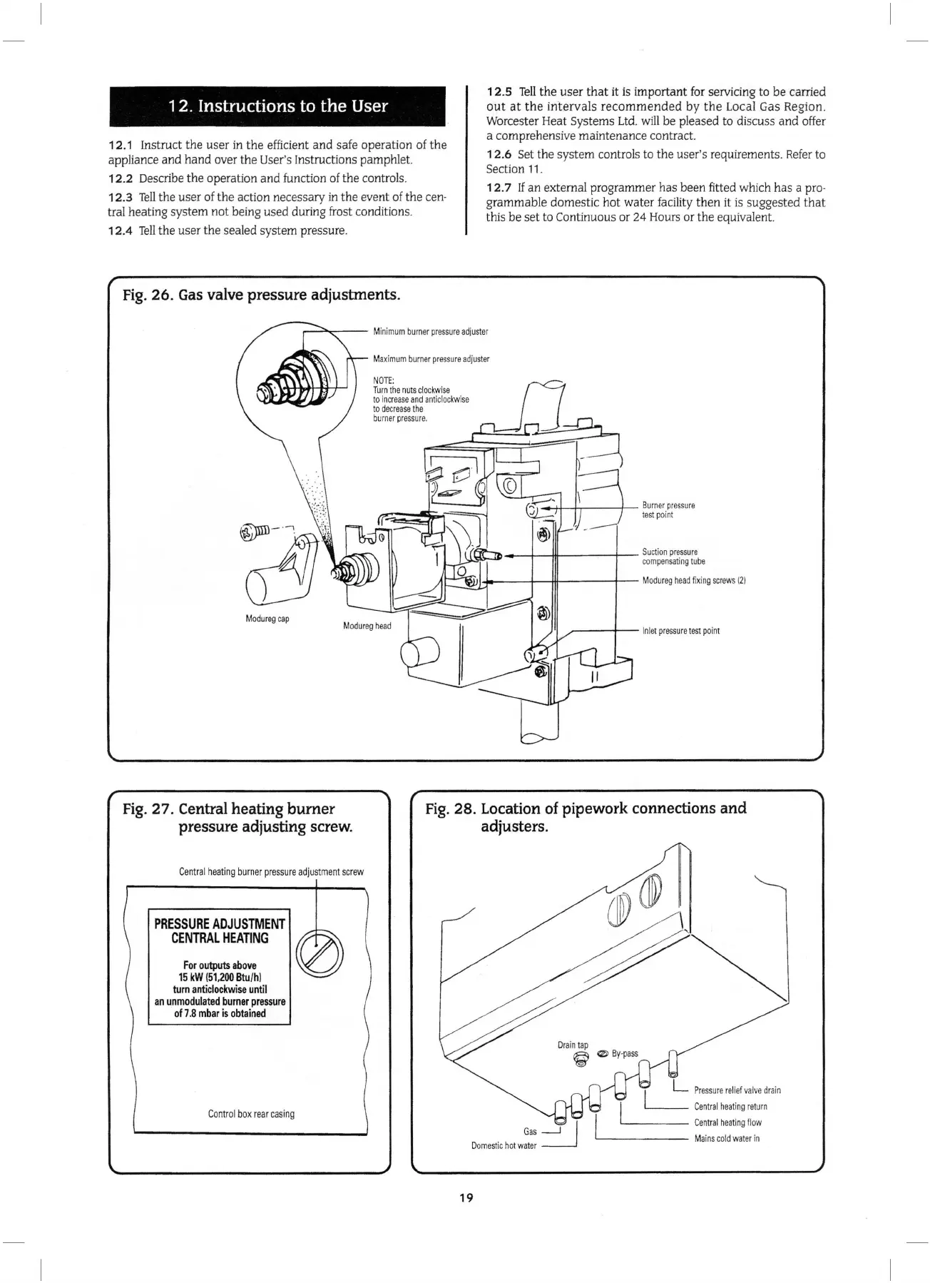
Fig
.
26.
Gas
valve pressure adjustments.
1 2.5
Tell
the user
that
it
is
important
for
servicing to be carried
out
at
th
e
intervals
recommended
by
the
Local Gas
Re
gion.
Worcester Heat Systems
Ltd
.
will
be pleased to
di
scuss and offer
a comprehensive maintenance contract.
12.6
Se
t the system controls to the user's requirements.
Refer
to
Section
11
.
12
.7
If
an external programmer has been fitted which has a pro-
grammable domestic hot water facility then it is suggested
that
this be set to Continuous or 24 Hours or the equivalent.
M
aximum
burner
pressure
adjuster
M
odureg
cap
Fig.
27.
Central heating burner
pressure adjusting screw.
Cent
ra
l
heating
burner
pressure
a
dju
stmen
t
screw
PRESSURE
ADJUSTMENT
CENTRAL
HEATING
For
outputs
above
15
kW
(51,200
Btu/hi
turn
anticlockwise
until
an
unmodulated
burner
pressure
of
7.8
mbar
is
obtained
C
on
tr
ol
bo
x
rear
casing
NOTE:
Turn
the
nuts
clockwise
to
incr
ease
and
anticlockwise
to
decrease
the
burner
pressur
e.
----1--111------+-
Suction
pressure
compensating
tube
r.:::~YH~--t--fft------j'---
Modu
r
eg
head
fixing
screws
(2)
~---+--
Inlet
pressure
test
point
Fig.
28.
Location of pipework connections and
adjusters.
19
L
Pre
ssure
re
l
ief
valve
dr
ain
'----
Central
heat
in
g
return
'--
---
-
Central
heating
flow
'---------
Ma
ins
cold
water
in