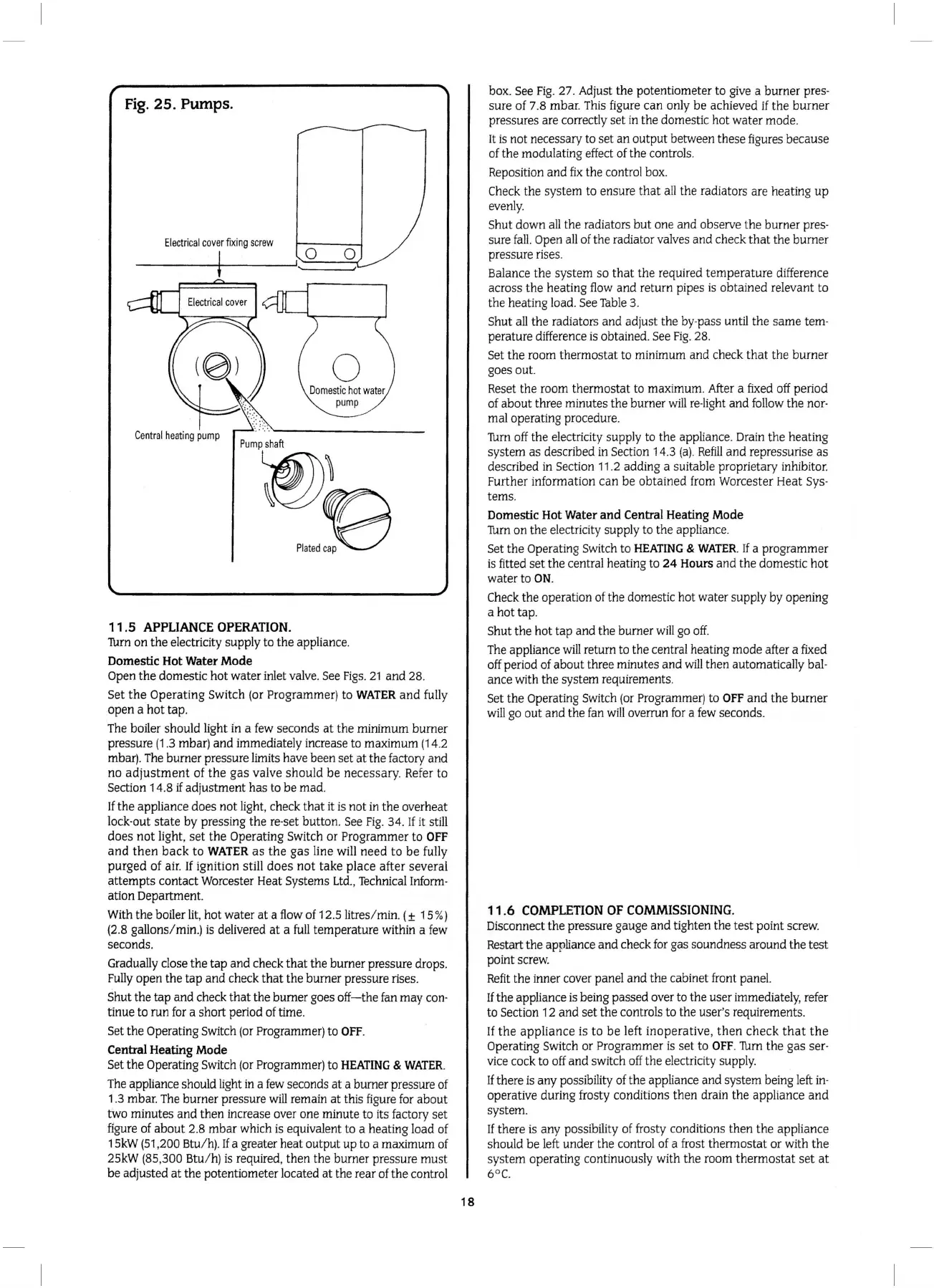
Fig.
25.
Pumps.
Electri
ca
l
cover
fixing
screw
0
0
Central
heat
ing
pump
11.5
APPLIANCE
OPERATION.
'fum
on
the
electricity supply to
the
appliance.
Domestic
Hot
Water
Mode
Open
the
domestic hot water inlet valve. See
Figs.
21
and
28.
Set
the
Operating Switch (or Programmer)
to
WATER
and
fully
open
a hot tap.
The boiler should light in a few seconds
at
the
minimum burner
pressure
(1
.3 mbar)
and
immediately increase to maximum (14.2
mbar).
The
burner pressure limits
ha
ve been set
at
the
factory
and
no
adjustment
of
the
gas
valve should
be
necessa
ry.
Refer to
Section 1 4.8
if
adjustment has to
be
mad
.
If
the
appliance does
not
light, check
that
it is not in
the
overheat
lock-out
state
by
pressing
the
re-set
button
. See
Fig
. 34. If it still
does
not
light,
set
the
Operating Switch
or
Programmer to
OFF
and
then
back
to
WATER
as
the
gas
line will need
to
be
fully
purged
of
air
. If ignition still
does
not
take
place
after
several
attempts
contact Worcester Heat Systems
Ltd.,
Technical Inform-
ation
Department
With
the
boiler lit, hot water
at
a flow of 12.5litres/ min_ ( ± 15%)
(2.8 gallons/ min.)
is
delivered
at
a
full
temperature within a few
seconds.
Gradually close the
tap
and
check
that
the
burner pressure drops.
Fully open
the
tap
and
check
that
the
burner pressure rises.
Shut
the tap
and
check
that
the burner goes
off
-
the
fan may con-
tinue to run for a short period of time.
Set
the
Operating Switch (
or
Programmer) to
OFF.
Central
Heating Mode
Set
the
Operating Switch (or Programmer) to
HEATING
&
WATER.
The appliance should light in a few seconds
at
a burner pressure of
1
.3
mbar. The burner pressure
will
remain
at
this figure for
about
tWo
minutes
and
then increase over one minute to its factory
set
figure of
about
2.8
mbar
which is equivalent to a
heat
ing load of
15kW
(51
,200 Btu/
h)
. If a greater
heat
output
up
to a maximum of
25kW
(85
,300 Btu/
h)
is required, then
the
burner
pr
essure
must
be
adjusted
at
the
potentiometer located
at
the rear of
the
control
18
box
. See
Fig
. 27. Adjust
the
potentiometer to give a burner pres-
sur
e of 7.8 mbar. This figure
can
only
be
achieved if
the
burner
pressures are correctly set
in
the domestic hot
water
mode.
It is not necessary to set
an
outp
ut between these figures because
of the modulating effect of
the
controls.
Reposition
and
fix
the
control box.
Check
the
system to ensure
that
all the radiators are heating
up
evenly.
Shut down all the radiators
but
one
and
observe
the
burner pres-
sure
fall.
Open a
ll
of
the
radiator valves
and
check
that
the burner
pressure rises.
Balance
th
e system
so
that
the
requir
ed
temperature difference
across
the
heating flow
and
return pipes is obt
ained
releva
nt
to
the
heating load. See
Table
3.
Shut
all
the
radiators and adjust the by-pass until
the
sam
e tem-
pera
ture difference
is
obtained. See
Fig.
28.
Set
the
room thermo
stat
to minimum
and
check
that
the
burner
goes o
ut
Res
et
the
room thermostat to
max
i
mum
. After a fixed off period
of about three minutes the burner w
ill
re-light
and
follow t
he
no
r-
mal operating procedure.
'fum
off
the
electricity supply to the appliance. Drain the heating
system
as
described in Section 14.3 (
a)
.
Refill
and
repressurise as
described in
Se
ct
ion
11
.2
adding a suitable proprietary inhibitor.
Further information
can
be
obtained from Worcester Heat Sys-
tems.
Domestic
Hot
Water
and
Central
Heating
Mode
'fum on
the
electricity supply to
the
appliance.
Set
the
Operating Switch to
HEATING
&
WATER.
If
a programmer
is fitted
set
the
central heating to
24
Hours
and
the
domestic hot
water to
ON.
Check
the
operation of the domestic hot water supply by opening
a hot
tap.
Shut
the
hot
ta
p
and
the
burner
will
go off.
The appliance
wi
ll
return to
the
central heating mode after a fixed
off period of
ab
o
ut
three minutes
and
will
then automatically bal-
ance with
the
system requirements.
Set
the
Operating Switch (or Programmer) to
OFF
and
the
burner
will go
out
and
the fan
will
overrun for a few seconds.
11.6
COMPLETION
OF
COMMISSIONING
.
Disconnect
the
pressure gauge
and
tig
hten
the
te
st
po
int screw.
Restart
the
appliance
and
check for gas soundness around the
tes
t
po
int screw.
Refit
the inner cover
pane
l
and
the
cabinet front panel.
If
the
appliance is being passed over to
the
user immediately, refer
to Section 12
and
set
the
controls to the user's requirements.
If
the
applia
nce is
to
be
left inoperative,
then
chec
k
th
at
the
Operating Switch
or
Progra
mme
r
is
set
to
OFF
. 'fum
the
gas
ser-
vice cock to off
and
switch off
the
electricity supply.
If
there is
any
possibility of
the
appliance
and
system being left
in-
ope
rative during frosty conditions
the
n drain t
he
appliance
and
system.
If
there is
any
possibility of frosty conditions
then
the
appliance
should
be
left under
the
control of a frost
thermostat
or wi
th
the
system operating continuously with
the
room
ther
mosta
t
set
at
6 0
(_
 Loading...


