13. Inspection
and
Servicing
13.1
To
ensure continued efficient operation of
the
appliance,
it
must
be
checked
and
serviced as necessary
at
regular intervals.
The frequency of servicing
will
depend upon the particular
in
stal·
lation conditions
and
usa
ge,
but
once per year
sh
ould generally
be
adequate. The extent of
the
service required
by
the appliance
is
determined
by
the
operating condition of
the
appliance when test·
ed
by fully qualified engineers.
It is
the
law
that
any service work
must
be
carried
out
by compe·
tent
engineers such
as
British Gas or
Corgi
registered personnel.
13.2
PRE-SERVICE INSPECTION.
Check
that
the
flue
terminal and
the
terminal guard,
if
fitted, are
clear.
If
the
appliance is in a compartment, check
that
the
ventilation
openings
in
the compartment door
or
wa
ll
s are clear. See Section
6.
Check
the
connections
in
the
system
and
remake any joints
or
fit·
tings which show signs of leakage.
Refi
ll
, vent
and
re·pressurise
as
described in Section
11
.
Operate
the
appliance
and
the
hea
ting system taking note of any
fault
s.
IMPORTANT
.
Dis
co
nnect
the
electrical supply
at
the mains
and
turn
off
the
gas supply
at
the
gas service cock on
the
appliance
before servicing. See
Fig.
21
.
After completing the service always test for gas soundness as
indi·
cated
in
BS
6891 .
13.3
DISMANTLE THE APPLIANCE.
To
carry
out
a full
and
comprehensive
serv
ice of
the
appliance
remove
the
following
parts
to
gain
access
to t
he
co
mpon
ents
which
need
to
be
checked
or
serviced:
(a)
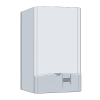
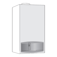
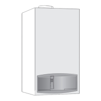
Cabinet Front
Cover.
Pull
forward at
the
bottom
and
lift
off
the
.
top
supports. See
Fig
. 22.
·
(b)
Inner
Cover PaneL Remove
the
cabinet front panel. Unscrew
the
four screws
and
remove
the
panel. See
Fig.
22.
·
(c)
Inner
Casing Cover. Remove
the
cabinet front cover. Unscrew
the
four screws
and
remove
the
casing cover. See
Fig.
22.
(d)
Combustion Chamber
Cover.
Remove the inner casing cover.
Loosen
the
two wing
nuts
securing the
flu
e hood and remove
the
hooks
from
the
combustion
chamber
cover. Unscrew t
he
four
screws
and
remove the cove
r.
See
Fig.
29.
(e)
Fan. Remove t
he
inner casing cover. Remove by unplugging
the electrical connections
at
the terminal block, pu
ll
ing off the sue·
tion pipes and unscrewing the single
fixing
screw. Unscrew the
flue
duct
fi
xing clamp. See
Fig
.
18
.
(a)
Appliance
with
Rear Flue. Carefully slide
the
fan
out
of
the appliance ensuring
that
the
flue
duct remains undisturbed.
(b)
Appliance
with
Side Flue. Carefully slide the
flue
duct out
of
th
e fan outlet, to
the
left
or
right
as
appropriate. Unscrew
and
remove
the
flue hood fixing hook
at
the same si
de
as
the
flue connection.
(f)
Flue Hood Assembly. Remove
the
inner casing cover.
Loo
sen
the
two wing
nuts
securing
the
flue hood and remove
the
hooks
from the combustion chamber cover. Withdraw
the
clamping bars
from their rear bracket
and
lift
the
flue hood assembly from the
appliance.
If
th
e fan is not
to
be
removed separately,
then
discon·
nect t
he
electrical supply,
the
suction tubes
and
the flue duct as
described in
the
pr
eceding note. See
Fig
. 15.
(g)
Burner
Blade Assembly. R
em
ove
the
combustion chamber
cover. Remove
the
spark
and
sensing electrode
asse
mblies by un·
screwing and removing the mounting brackets complete. See
Fig
.3
0.
Loosen
the
two bottom fixing screws and unscrew and remove the
two extended screws securing the burner blade assembly. See
Fig.
31
.
Lift
the
blade assembly off
the
bottom support screws, raise
the
front of
the
assembly
to
abo
ut
45
°
and
carefu
ll
y withdraw
it
from
the
combustion chamber.
Take
care
not
to damage
the
insu·
Iation
pad
s.
20
1
3.4
SERVICING OF COMPONENTS.
Clean
the
fan. Any
dus
t of
fluff
should
be
re
mo
ved with a
so
ft
brush or
by
blowing. Sharp instruments
must
no
t be used.
Take
care
not
to
distort the sensing tubes.
Clean
the
burner
. Brush
th
e bla
de
tops with a soft
brush
and
check
tha
t
all
the
flame
ports
are clear. Remove any blockages
with a non-metallic
bru
sh. Clean
any
deposits from t
he
ven
tur
is
using a soft
bru
sh.
Clean
the
electrodes
. Brush any deposits from
the
electrodes
using a soft
bru
sh. Replace any electrode
th
at
show
signs of dam·
age or erosion.
Clean
the
burner
manifold. Inspect t
he
injectors
and
carefully
clean with a soft brush.
Do
not
use a wire brush
or
anything like
ly
to
cause damage. Replace any injector which appears
damaged
.
Don't forget
the
spacing washer
s.
Clean
the
Gas
to
Water
heat
exchanger. Cover
th
e burner mani·
fold with a cloth. Clean
the
heat
exchanger using a soft
brush
.
Remove
the
deposits from the bottom of
the
combustion chamber.
Check
the
combustion
chamber
insulation. Examine
the
insu-
lation
pad
s
and
replace
if
necessary. See Section
14
, Para. 14.4.
Clean
the
controls. Remove any
dus
t or deposits wh
ic
h
may
have
built up
on
the
controls.
Ta
ke care not to mishandle
any
ca
mpo
·
nent
connections.
Reassemble
the
appliance.
Refit
the burner blade assembl
y,
the
e
lec
trodes,
the
flue hood and
the
fa
n
if
it
ha
s
been
removed
separate
ly. Check
that
the
elec·
tra
des
and
suction tubes are connected
and
positioned correctl
y.
See
Fig
.
30
.
Refi
t the combustion chamber cover. Carefully reconnect the flue
duct to
the
fan outlet
as
described in Section 11, Para. 5.
Check
that
a
ll
the
connections have been
made
correctly before
refitting
the
boiler inner casing cover. See F
ig
. 22.
Check
that
the
flue terminal
is
clean and unobstructed .
13.5
TEST THE APPLIANCE.
On
completion of
the
service
and
reassembly of
the
appliance,
check f
or
gas soundness
and
the
correct operation of
the
appli·
ance as described
in
Section
11
.
Refit
t
he
inner cover panel
and
the cabi
ne
t front
pane
l
and
reset
t
he
controls
to
the
user's requirements.
 Loading...


