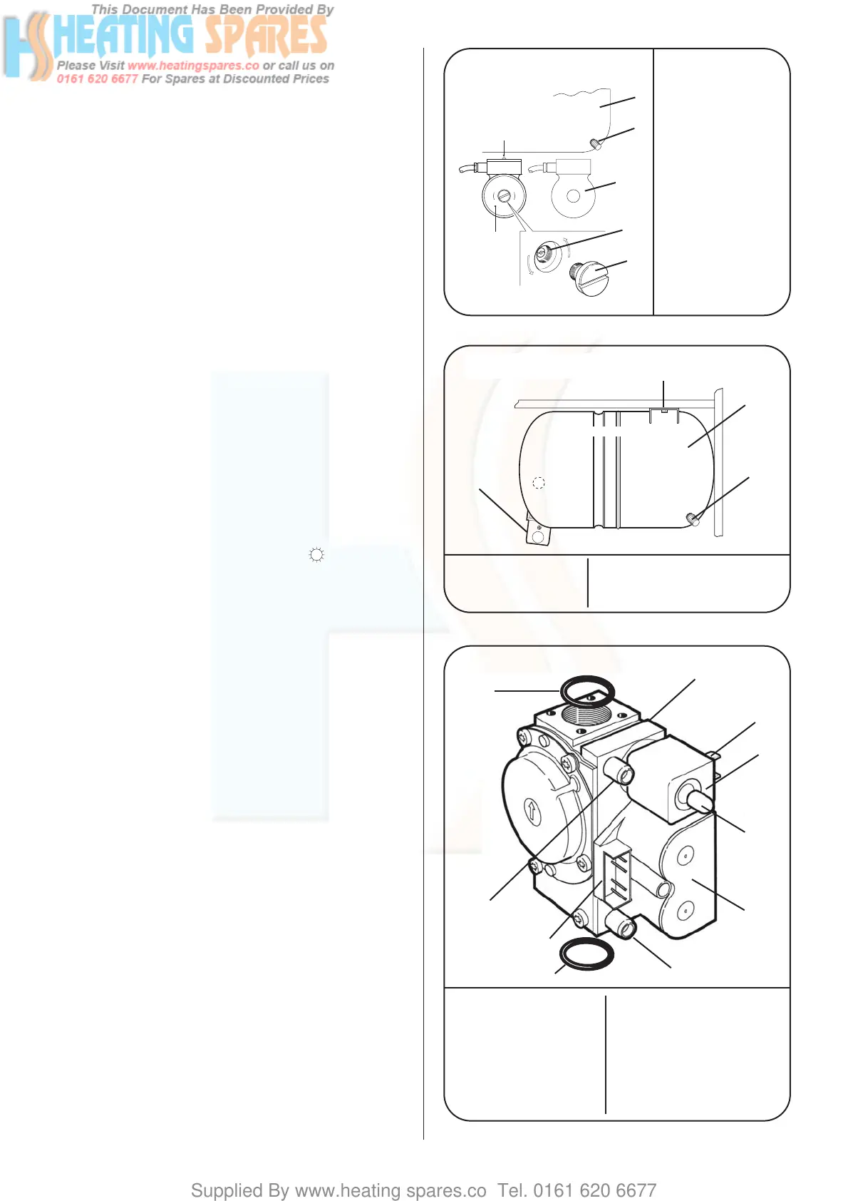
12.6. Remove the cap from the front of each pump and turn the
exposed shaft about half a turn using a flat bladed screw driver.
Replace the caps. Refer to Fig 38.
12.7. Set the system pressure by filling the system until a
pressure of 1.5 bar shows on the gauge and check for water
soundness. Release water from the system through the pressure
relief valve until the system design pressure is obtained.
System pressure in bar = Static head + 0.3.
Note 1bar = 10.2 metres of water.
The minimum system pressure should be 1bar.
Set the movable pointer on the gauge to coincide with the
indicating pointer as a permanent record of the set system
pressure.
12.8. The charge pressure of the expansion vessel must not be
less than the static head at the vessel. The initial charge pressure
of the expansion vessel is 0.5 bar (static head of 5 metres). A
schraider type valve is fitted to the vessel for the charge pressure
to be increased if necessary. Refer to Fig 39.
12.9. Refer to BS7074:1, BS5449 and Table 8 for details of the
allowable system capacity.
If the system volume is greater than that which can be
accommodated by the expansion vessel on the appliance then
an extra vessel must be fitted as close to the appliance as
possible in the return pipe.
12.10. Clock/Programmer: The controls fitted to the appliance
should be set at this stage. Detailed instructions are sent with
the control.
12.11. Check that the gas supply is turned off.
12.12. Connect a pressure gauge to the gas valve. Refer to Fig 40.
12.13. Check that the electricity supply is off.
12.14. Set the external controls and the domestic hot water
temperature control knobs on the facia to maximum. The central
heating temperature control must be set at off ( ).
12.15. Turn the gas on at the service cock. Refer to Fig 26.
12.16. Turn on the electricity supply to the appliance. Refer to
Fig 37.
12.17. Open the domestic water inlet valve and fully open a hot
water tap.
12.18. Check Pressure. The boiler should light at minimum
burner pressure of 1.5mbar (G20) or 6.0mbar (G31) and
immediately increase to a maximum of 14.2mbar (G20) or
34.7mbar (G31). The pressures have been set at the factory and
no adjustment of the gas valve should be necessary.
If the maximum pressure is not correct then check that the inlet
pressure to the appliance is 20mbar (G20) or 37mbar (G31). Refer
to Section 9.3.
If the burner does not light then check the overheat thermostat
by pressing the reset button on the facia. Refer to Fig 37. If it still
does not light then turn the hot water tap on and off a few times
to purge the gas line of air. If ignition still does not occur after
several attempts then contact WHS Technical Information
Department, Telephone 0990 266241.
With the boiler alight hot water at a rate of upto 12.6 (±15%)
litres/min will be delivered at full temperature after a short
warm up period.
Slowly close the tap and see the burner pressure drop.
Fully open the tap and the pressure should rise.
Shut the tap and check that the burner goes off, the fan or pump
will continue to run for a short period.
12.19. Set the central heating temperature control to maximum.
12.20. The burner should light at the minimum burner pressure
and remain at this figure for about two minutes and then
increase over a 1 minute period to a pressure equivalent to a
heating load of 25kW. The output will then automatically adjust
to the system load.
Check that all the radiators are heating evenly. Shut down some
of the radiators and see the burner pressure fall and rise again as
they are re-opened.
18
Fig 38-Pumps
Fig 39 Expansion Vessel
Fig 40-Gas Valve
2
1
7
6
5
3
4
1. Central Heating
Pump
2. Electrical
Connection Cover
Fixing Screw
(not accessable with
the pump in-situ)
3. Expansion Vessel
4. Charging Valve
5. Domestic Hot
Water Pump
6. Pump Cap
7. Impeller
Adjustment
4
1
2
3
1. Expansion Vessel 3. Fixing Clip - UP to Release
2. Charging Valve DOWN to Lock
4. Fixing Screw
1
2
3
4
5
6
9
1. Gas Valve 6. Solenoids
2. Connector 7. Inlet Pressure Test Point
3. Connections 8. Burner Pressure Test Point
4. Modulator 9. 'O'Rings
5. Pressure Adjustment
(shown with cap in place)
7
8
9