10.10. On very rare occasions an external frost thermostat might
be considered where parts of the system are remote from the
appliance. Refer to Worcester Heat Systems Technical
Department for more information - Tel: 0990 266241.
10.11. A radio frequency room thermostat is available for use
with the appliance.
10.12. Safety check: If there is an electrical fault after installation
check for fuse failure, short circuits, incorrect polarity of
connections, earth continuity or resistance to earth.
9
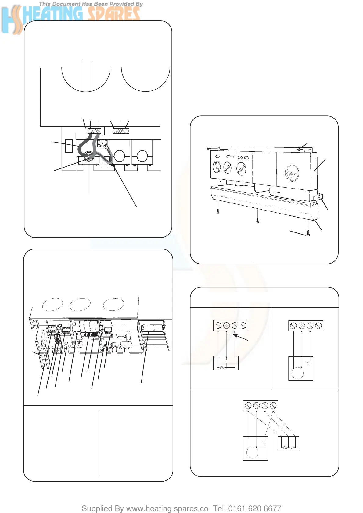
Fig 9 - Mains Electrical Connection
Fig 10 - Electrical Connections
230V
ST12
L N Ns Ls LR
Brown
Blue
Strain relief clamp
Green/Yellow
13
1
2
3
4
5
6
7
8
9
10
11
12
1. ST12-Mains 9. Fuse-F2
2. Fuse-F1 10. Cable Entry Clamp
3. Earth Screw 11. ST13-24volt Controls
4. ST8-Room Thermostat (not used)
and External Control 12. Main Harness and Clamp
-Mains Voltage 13. Control Panel Pivot
5. Cable Entry Screw Clamp Point
6. Earth Tag
7. ST15-Pump
8. ST1-Fan
Fig 11 - Facia Connections Cover
1
2
3
4
5
1. Control Panel Fixing Screws
2. Facia
3. Control Panel Pivot Point
4. Connection Cover
5. Connection Cover Fixing
Screws
Fig 12 - Mains Voltage External Controls Connections
230 V Room Thermostat Connections
Ns
Ls
L
R
Spare
ST8
Ns
Ls
L
R
Spare
ST8
Remove Link
Neutral
Live
Switched Live
Neutral
Live
Switched Live
Motor
230 V Programmer Connections
230 V room thermostat and
Programmer Connections
Ns
Ls
L
R
Spare
ST8
Neutral
Live
Switched Live
Neutral
Live
Switched Live
Motor