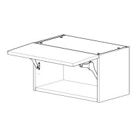
WALL UNIT
600 - 800 Lift
Assembly Guide
For Internal Use: FI.WR.INS.032_WKIN00121_WALL_600-800_Lift_Rev4.indd
Page 2
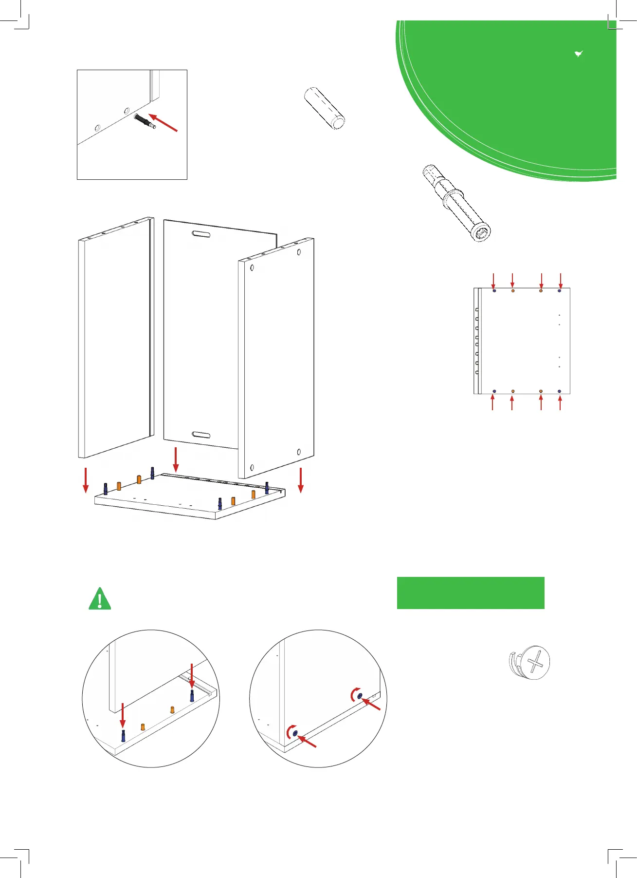
Step 1.
Seat dowel (F)
into holes in
end panel (B) as
shown.
Step 2.
Seat cam dowel (G)
into holes in
end panel (B) as
shown.
Step 3.
Attach panels x2 (C) to panel
(B), using cam dowels (G)
& cam locks (H) (in blue),
and also using dowels (F)
(in orange) in positions as
shown.
Step 4.
Slide panel (A) into the groove
of panels (B) and x 2 (C).
Step 5.
Insert cam lock (H).
Hand tighten all cam locks
(H), this will expand the
cam dowels (G) and tighten
the unit together.
All Cam Locks (H) are to be positioned facing the
outside of the unit carcass, for ease of tightening.
Do not use power tools with
cam dowel (G) or cam lock (H)
Dowel (F)
& Cam Dowel (G)
location detail
G
G
F
F
F
F
G
G
B
A
C
C
B
B
B
C
C
H
H
G
G
View from underside View from underside
Seat (G)
cam dowel
into hole as
shown.