P. 4 / 12
Profibus DP – CBF-B1/CBFF-B1 Burner Control Box
vor00161
Device specific parameters must be considered during PROFIBUS-DP system configuration. In order to simplify this proc-
ess, CBF-B1/CBFF-B1 control boxes are supplied with a data file containing these parameters (GSD). The file format is
standardized and recognizable by other Profibus devices (masters/slaves). The bus interface will remain operable (online)
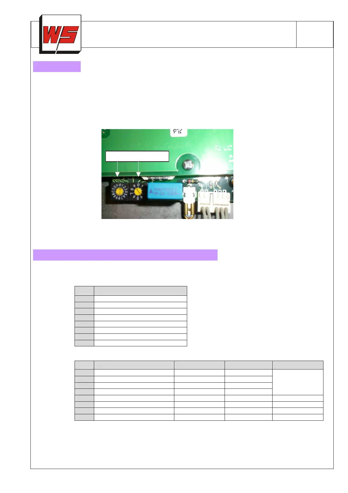
even if the CBF-/CBFF-B1 is turned off (stand-by mode) The setting of the Profibus addresses can be done by using the ad-
dress selector switches within the Profibus control box (Picture 2).
Picture 2 – Profibus address selectors:
Following tables showing data transmission between master and slave (CBF-B1/CBFF-B1).
Tab.2 : Output byte ( Master → CBF(F) :
Bit Output byte AB0
0 Remote reset
1 Start (heat demand)
2 Cooling
3 Air purge
4
5
6
7
Tab.3: Input bytes (CBF(F) → Master ):
Bit EB0 EB1 EB2 EB3
0 Operation burner Manual mode Status byte*
1 Fault burner Cooling valve ON
2 Air valve ON Safety interlock
3 Purge air ON open
µA-flame signal
0...255,
255=25,5µA
4 Cooling ON open
5 Flame mode ON (CBFF) open
6 FLOX mode ON (CBFF) open
7 Stand-by open
*) see Tab.4
Address selector switches
( i.e. address 116 : B (11x 10
) + 6 (10
) = 110 + 6 = 116 )
Data Transmission (Bytes/Bits) from Master to CBF(F)
 Loading...