P. 5 / 12
Profibus DP – CBF-B1/CBFF-B1 Burner Control Box
vor00161
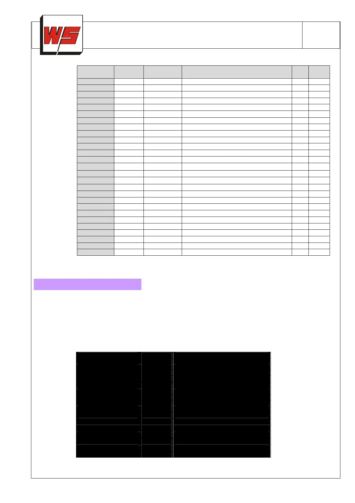
Tab.4: Status byte EB2 – Signal Referencing ( CBF(F) → Master):
Byte
(decimal)
Display static= S
flashing = B
Text CBF
CBFF
0
00
S Ready x x
1
A1
S Waiting time x x
2
A2
S Safety time during start-up x x
3
A3
S Flame stabilizing period x x
4
A4
S Flame mode x x
5
A5
S FLOX mode x
6
P0
S Air purge x x
7
C0
S Cooling x x
8 Reserve
9 Reserve
10
00
B
Proof of Closure (USA)
x x
11
A1
B False flame signal x x
12
A2
B Start up without flame signal x x
13
A3
B Loss of signal during stabilizing period x x
14
A4
B Flame failure x x
15
d0
B Delta-p switch failure x
16
d2
B Start up without air pressure x
17
d3
B No air pressure during stabilizing time x
18
d4
B No air pressure in Flame mode x
19
dP
B No air pressure during purge x
20
10
B Remote reset limit exceeded (5x/15 min)**
x x
21
d5
B No air pressure in FLOX mode x
22
FF
B FLOX-Flame switching fault x
51
51
B Defective fuse f1 or safety interlock x x
52
52
B Permanent remote reset signal x x
53
53
B Cycle time too short x x
54
54
B Manual operation: Flox locked out x
**) „10“ will flash in display if more than 5 remote resets were attempted via the bus within 15 minutes. Further remote
resets are not possible, burner must be reset manually at the burner control box. ( Limitation is implemented to prevent
continuous resetting in case of a bus failure) Local reset will re-enable remote reset.
During operation the 7-segment display will show the current program status. Flame signal strength and other parameters
will be displayed by repeatedly pressing the Reset/Info button.
Should a fault occur, the CBF-/CBFF will terminate operation and display a flashing fault code. Meaning of fault code can be
determined from fault schedule attached to front of control box (see Fig. 2) Fault schedule is available in several languages
and can be exchanged easily. CBF-/CBFF DP will display „- -„ signalising stand-by mode if the box is turned off. The bus
system will remain functional to enable communication to other devices. Control outputs of CBF-B1/CBFF-B1 (ignition, sole-
noid valves) are electrically separated from the power supply.
Fig. 2 : Fault Schedule (English):
Permanent
Display
Blinking
Start position
00
Waiting time
A1 Flame signal at start
Safety time on start-up
A2 Flame failure during start-up
Flame proving period
A3 Flame failure during proving period
Normal operation flame
A4 Flame failure during operation
Normal operation FLOX
A5
dx Failure pressure switch
FF Failure FLOX-flame switching control
Purge
P0
Cooling
C0
51 Fuse F1 fault or safety chain interlock
52 Permanent remote reset
53 Cycle time too short
54 Manual operation: FLOX mode locked
Pb Bus fault
Power switch off
- -
dimensions: 83x44,25mm
 Loading...