DUSX^Ydb_^D" % GU \T3_^db_\
FUbcY_^F! !Q^TF! !1
%
'! "$$
',36ZLWFKHV
)HDWXUH&RQILJXUDWLRQ6ZLWFKHV
The T2050 has two sets of feature configuration switches. They
appear in two different forms:
• The first form is considered a virtual set of switches and are
located in the EPROM U17 at address $0206 and $0208. The
setting of the virtual switches may affect the features of the
DIP switches SW1. A control running firmware version V1.01
will display 77 at power-up. In V1.01, the feature choices of
SW1 are listed in Figure 2 below.
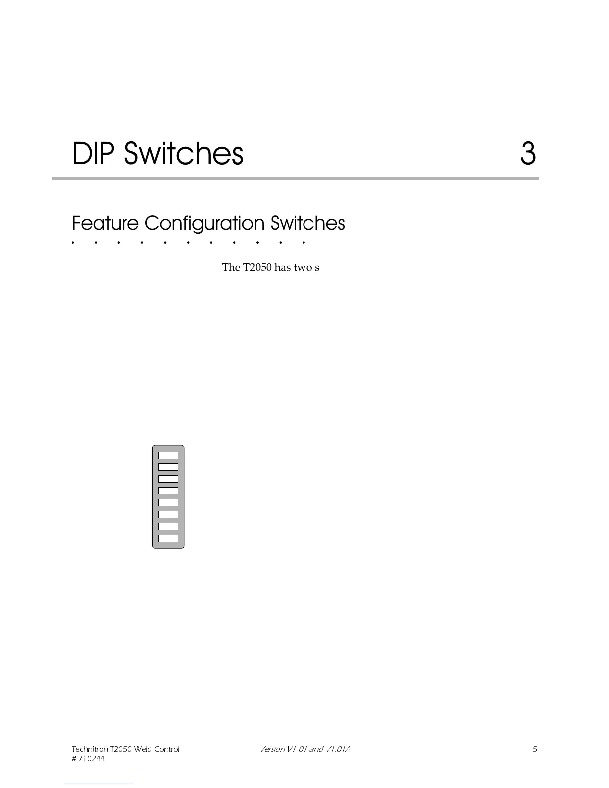
• The second set of switches are DIP (dual in-line package)
switches. These are on the controller PC board at SW1.
Figure 249@CgYdSXUcF! !
4Yc`\Qi-''
A control running firmware version V1.01A will display 79 at
power-up. Figure 3 on page 3-6 lists in V1.01A the feature choices
of SW1. The difference is switch #3, when closed the PS/SS input
will reset all stepper programs. Therefore, Pressure Switch mode
is not available in V1.01A.
C = ACCESS YELLOW CONFIG
C = BINARY VALVES
C = DISPLAY SCHEDULE
C = HYPERSIL WELD TRANS.
C = RESET FAULT BY PILOT
C = PRESSURE SWITCH
C = BINARY INITIATION
C = CONSTANT CURRENT
0 = ACCESS YELLOW DENIED
0 = DISCRETE VALVES
0 = DISPLAY LAST CURRENT
0 = STACKED IRON WELD TRANS.
0 = FAULT NOT RESET BY PILOT
0 = SECOND STAGE
0 = DISCRETE INITIATION
0 = AVC MODE WELD
 Loading...