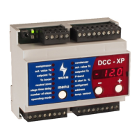
DCC-XP V6
Rack control
with integrated condensation pressure control
Page 4 of 4 Subject to technical changes DCC-XP_V6.5.0_PI_2021-08_EN
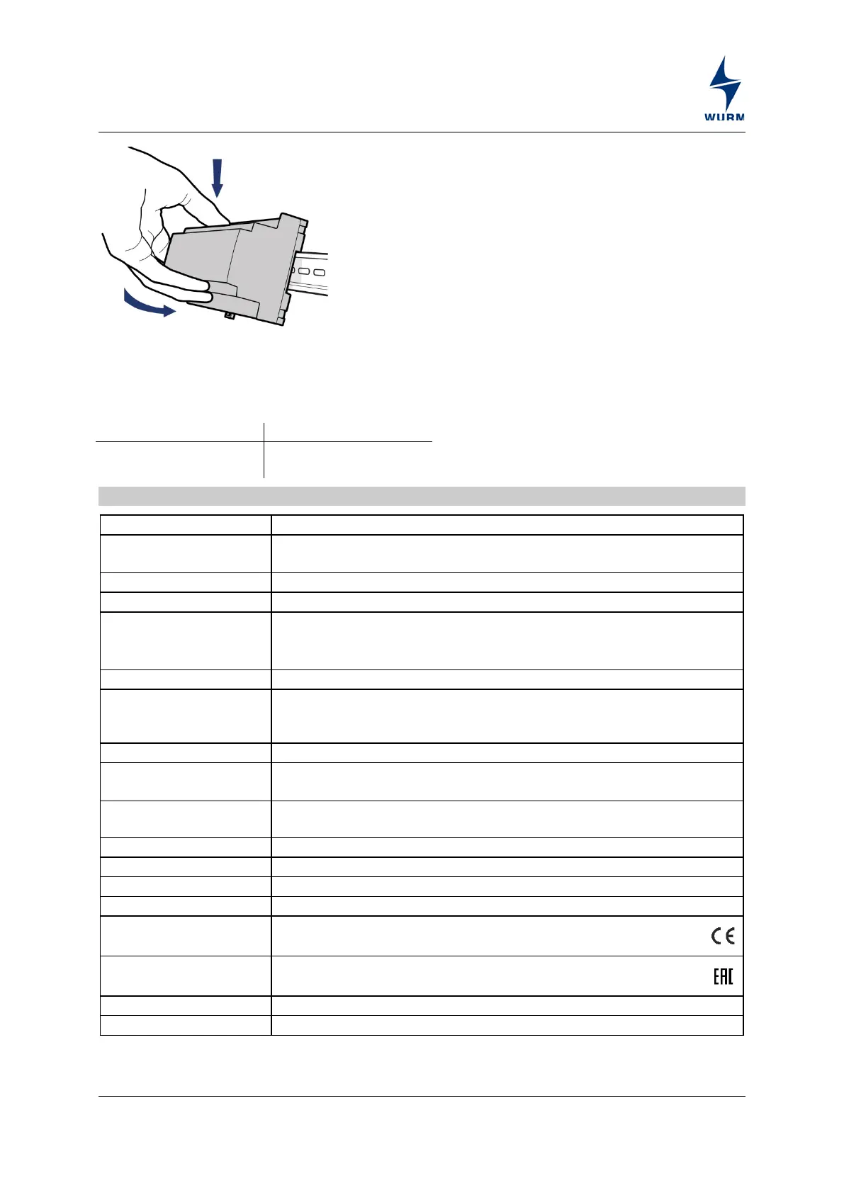
Place the device with the upper guide edge
on the top-hat rail.
Then press the device gently downward until
it engages with the fastening safety catch on
the top-hat rail.
For wiring of the data lines, we recommend the use of standard telephone lines 2x2x0.8ø up
to lengths of 100m. The shielding must be grounded in the control cabinet. For cable lengths
from 100m to 400m, shielded lines with braided sheathing should be used.
We recommend the use of shielded cables for sensor extension.
Technical data
230V~, +10% / -15%, 5VA approx.
0
: -0.5...7bar (corresponds to 4...20mA);
p
c
: 0...25bar (corresponds to 4...20mA)
0...10V= (for output control in voltage control operating mode)
Digital inputs
floating
1 x setpoint increase (∆T
0
), 1 x Fastreturn (FR)
2 x peak load shedding (I and II) of which 1 x multifunctional input (II)
4 x normally open contact, 230V~, 4(2)A, rated voltage 230V~
0...10V=, non-isolated, max. load 10mA, for connection of ADC
(multiple contact switch), speed regulator or frequency converter for
condensation pressure control
Single-chip microcomputer, data memory
Monitoring of connected sensors,
Self-monitoring of data memory and microcomputer
3-wire CAN bus interface with integrated power supply, galvanically
isolated, service socket
(WxHxD) 106 x 90 x 58mm (DIN 43880)
Top-hat rail TH 35-15 or TH 35-7.5 (DIN EN 60715)
Operation: 0...+55°C, storage: -25...+70°C
CE conformity
− 2014/30/EU (EMC Directive)
−
2014/35/EU (Low Voltage Directive)
EAC conformity
−
 Loading...