9
Tool Specifications
Electromagnetic compatibility (EMC)
This product is manufactured conform to the current EMC standard. Please
notice following items:
❏
The unit is for welding under commercial or industrial conditions. The
use in other surroundings (for example in residential areas) may dis-
turb other electric devices.
❏
During welding electromagnetic problems can be caused at:
– Mainscables, controlcables, connections for telecommunication
– TV/Radio
– Computer and other similar devices
– Protection devises as for example alarm systems
– Pacemakers and hearing aids
– Devices for measure and calibrate
– Devices with less protection against disturbances
If other devices are disturbed it may be necessary to protect addition-
ally.
❏
The affected area can be bigger than your premises/property depends
of the building etc.
Please use the unit conform to the instructions of the manufacturer. The
user is responsible for installation and use of the machine. Furthermore the
user is responsible to eliminate the disturbances caused by electromagnet-
ic fields.
Brief Instruction
❏
Plug mains plug into socket.
❏
Connect ground cable and electrode holder to the connection sockets
3
and
4
.
❏
!! Caution: Observe the polarity according to the information of the
electrode manufacturer (also see Electrode Welding).
❏
Clamp stick electrode to electrode holder.
❏
Switch on the unit at the main switch
6
.
❏
Set the desired welding current with the output regulator
10
.
❏
The unit is ready for welding.
Before operation
Transport
Before transporting the unit, always pull the mains plug.
Always carry the unit by the carrying strap.
Set-up
Place the unit securely on a horizontal, dry surface. Pay attention that the
ventilation slots of the cooling fins are not obstructed at any time.
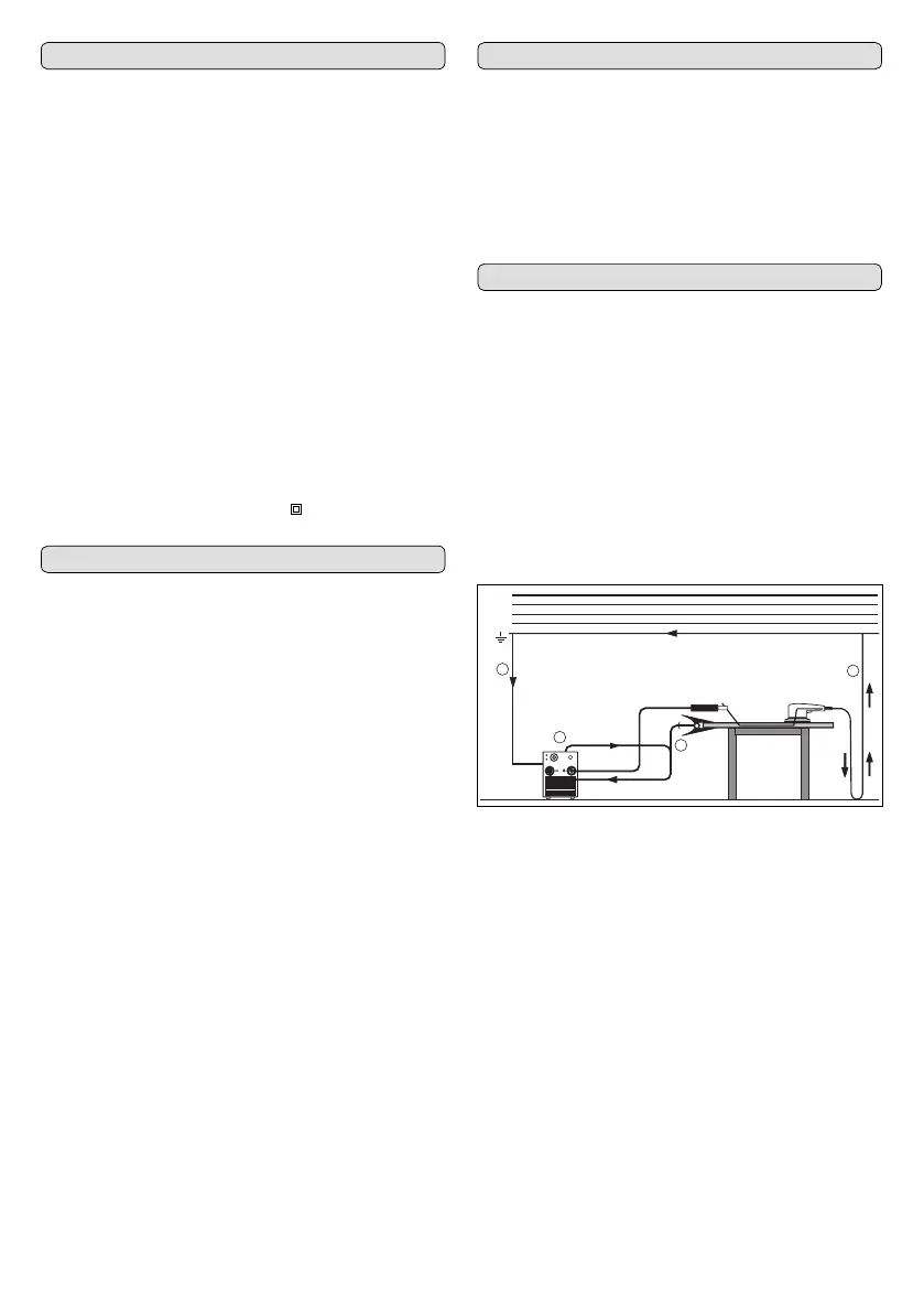
Connecting the Ground Cable
When selecting the working location, pay attention that the ground cable
and the ground/welding clamp can be attached properly.
The ground/welding clamp must be attached to a blank location of the
welding table or workpiece, ensuring good conductance. This must be in
the direct vicinity of the welding spot, so that the welding current cannot
take its own return path via unit components, ball bearings or other elec-
trical circuits.
➀
Do not lay the ground/welding clamp on the welder or the gas cylin-
der, because otherwise the welding current is led via the protective con-
ductor connections and destroys these.
➁
Firmly connect the ground/welding clamp to the welding table or the
workpiece.
Connecting to the Mains Supply
Before putting the unit into operation, make sure that a suitable mains
connection is available. The fuse protection must correspond with the tech-
nical data.
Unit Type ESI 150
Article number 0702 351 0
Welding range, electrode/TIG 5 – 150 A
No-load voltage 85 V
Power adjustment variably
Duty cycle 100%, 40 °C 100 A
Duty cycle 60%, 40 °C 125 A
Duty cycle at max. power, 40 °C 35 %
Electrode diameter max. 4 mm Ø
Mains voltage 230 V
Mains frequency 50/60 Hz
Mains fuse 16 A/tr
Max. current consumption I1 26,6 A
Max. power consumption S1 (100%) 6,1 kVA
Power factor 0,99 cos
ϕ
Mains connection
1,5 mm
2
Mains plug 16 A
Protection class (IEC 529) IP 23
Cooling F
Dimensions (L x W x H) 337 x 130 x 211 mm
Weight 5,25 kg
Protection class
/
II
2
1
1
L1(R)
L
2(S)
L
3(T)
N(MP)
PE
1

 Loading...