Copyright © Vertical Leisure Ltd. 2017 | All rights reserved. Version: 1.02
13
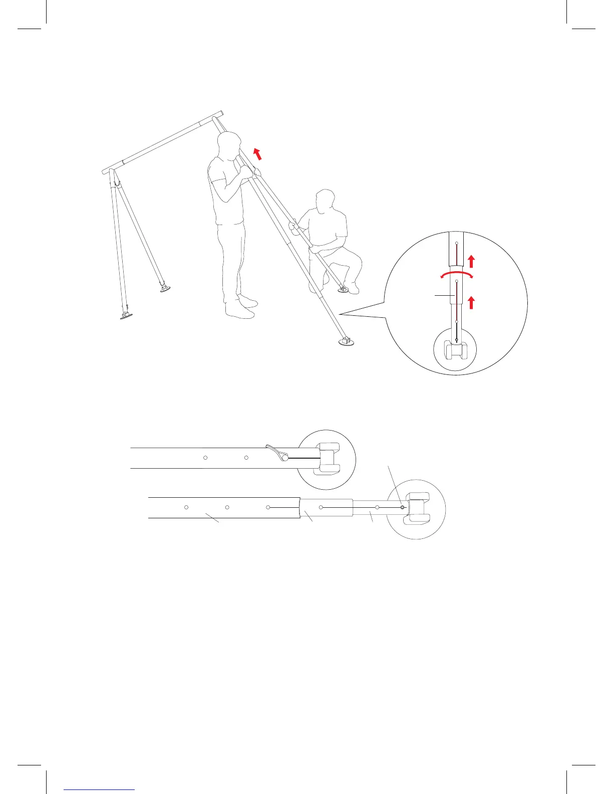
EXTENSION OF LEGS
When the A-Frame is delivered, the legs will be set at minimum height (for easy transportation).
Note: Remove the bottom pin or pin nearest to the foot to expand the legs. Then replace pin when in desired position. Do
not extend completely or legs will come apart or get jammed. A second pin will be required to extend the leg - if you
over-extend the legs you will see a white stop cap - do not ever exceed this point.
Note: Go around the A-Frame and visually check that all the pins are inserted and locked securely.
(Head of Pin outside)
Please remember: Top Legs extend rst, then middle, then bottom.
Guide line to
align holes.
Fig 2.8
Fig 2.9
Remove both pins at one side of the A-Frame, as illustrated in gure: . With one person lifting – the legs can then be
extended and pinned back into position (please ensure that the pins are positioned in the inside of the A-Frame & the
legs are pinned back into position using the adjustment line to align).
Repeat this process on the opposite side. Please ensure both sides are level and extended evenly.
To lower the A-Frame, the reverse of this procedure must be repeated exactly the same on all four legs.
Final clip needs to be placed just above the feet on all four legs – this will later be used for further stabilisation using the
sandbags.
1
2
3
4
Top Leg Middle Leg Bottom Leg
3mm Hex Screw
 Loading...