Copyright © Vertical Leisure Ltd. 2017 | All rights reserved. Version: 1.02
8
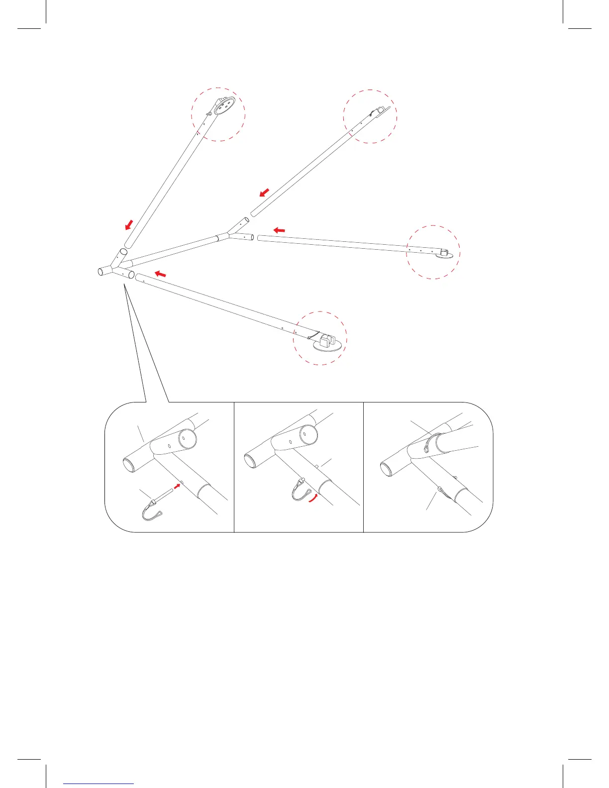
ATTACHMENT OF LEGS
1. Lay the top bar on the ground as illustrated in Fig. 1.8
2. Insert the leg starting with the hole at the bottom in the Leg Connector. Place the leg into the Leg
Connector and line up the holes on the legs with the holes in the Leg Connector. There will be a
‘guide’ line etched on the legs to help with this process.
3. Once the leg has been fully inserted, secure it using the lock pin.
4. Once the rst leg is secure, now repeat the process in the order illustrated in the diagram –
following numbers 1 to 4. (Fig. 1.8 and 1.9.)
Note: Head of the pin on the outside of the legs and tail being on the inside.
Head of Pin
Leg Connector
Tail of Pin
Head of pin outside of A-Frame
Hook outside of A-Frame
1
2
3
4
Fig 1.8
Fig 1.9
 Loading...