System Components
X16
plus
Quick Start Guide
EKT8 Card
Standard Digital
Telephone
VOIP Card
CO2 Card
IP8g IP Telephone
IP9g IP Telephone
DECT Cordless
IP Phone
& DECT Base
Add-on DECT
Cordless IP
Phones
Items vary depending on bundle purchased. Expansion cards are installed before shipment on some bundles.
Ethernet
Data
Cable
Tel Lines Cords
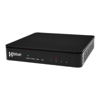
X16
plus
Server
Add-on DECT Cordless
IP Speakerphone
Equipment Room
Wiring
Telephone System Wiring/Cabling must be “Home-Runs”. This means that each telephone location
must have a cable from that location to where the server is located (equipment room).
X16
plus
base configuration has 8 ports for Standard Digital Telephones and allows for expansion to 16
Standard Digital Ports with the optional EKT8 Card.
When the optional VOIP Card is equipped X16
plus
supports up to 16 IP devices. When both digital and
VOIP phones are used the X16
plus
maximum configuration is 32 phones.
• Standard Digital Telephones (16 max) must be cabled using Cat3,4,5 or 6.
• IP Phones must be cabled using Cat5e, 6 or greater. IP Phones can be installed on existing com-
puter (Ethernet Cat5e or greater) cabling!
• IP Phones can be connected to the server wirelessly using the WIFI Dongle (optional). WIFI should
only be used when necessary. WIFI is often NOT RELIABLE and is NOT RECOMMENDED as a
total system installation solution.
• Bluetooth for headset use is built into IP8g and available on the IP9g using an optional BT Dongle.
WIFI Dongle
Connect XD10 (Standard Digital) Telephones
X16
plus
Server
Use UTP (Unshielded Twisted Pair) cable. The
center two pins of the RJ11 wall jack and plug are
used. Connect one “PAIR” to the center two pins at
the wall jack. Use the White/Blue-Blue/White pair.
• White/Blue to GREEN
• Blue/White to RED
At the RJ11 plug insert the White/Blue, Blue/White
pair into the center two pins and crimp the connector.
(Connectors and crimping tool can be purchased at
Home Depot.) Then insert the RJ11 into X16
plus
XBLUE Digital Phone Ports 1-8. Each port operates
one XD10. Ports 9-16 are optional.
You may be able to use cables that are
already in place. Usually telephone cables
are terminated on 66 Blocks (see pic).
Determine if the compexity of using existing
cables is more than you want to do. If so,
you can find telephone cable installers who
can help.
To determine if the person is up to the task
ask them to describe the “66 Block” to you.
If they cannot, pick someone else.
Make sure there are
NO OTHER
devices or terminals on the wires
that go from the Digital Port to
the XD10 telephone!
RJ11 Wall
Jack
RJ11 Plug
66 Block
There are 6 pin positions in a
RJ11. Only the two in the
center are used for XD10
Telephones.
Page 1/2
X16plus-QSG v2
Bluetooth Dongle