V5 series inverter
52
P0.03 Running command channel selection Range: 0, 1, 2 0
0: Panel control
Use to stop, start the inverter.
1: Terminal control
Use external terminal FWD, REV, X1~X6 to start or stop the inverter.
2: Serial port control
To start or stop the inverter via RS485 port.
Note: The control modes can be set by P0.03, please be careful to use this method during operating.
P0.04 Set running direction Range: 00~11 00
The lowest bit of this parameter is valid only for panel jog command channel.
Lowest bit of LED:
0: Jog forward in panel control mode
1:Jog reverse in panel control mode
Ten bit of LED:
0: Reverse running is permissible.
1: Reverse running is suppressed. The inverter will stop output when there is reverse command.
P0.05 Run forward/reverse dead time Range: 0.0~120.0s 0.1s
It is the transition time when output zero frequency during the inverter switch from forward to reverse or reverse to for-
ward, as shown in Fig.4-1 t
1.
Fig. 4-1 Run forward/reverse dead time
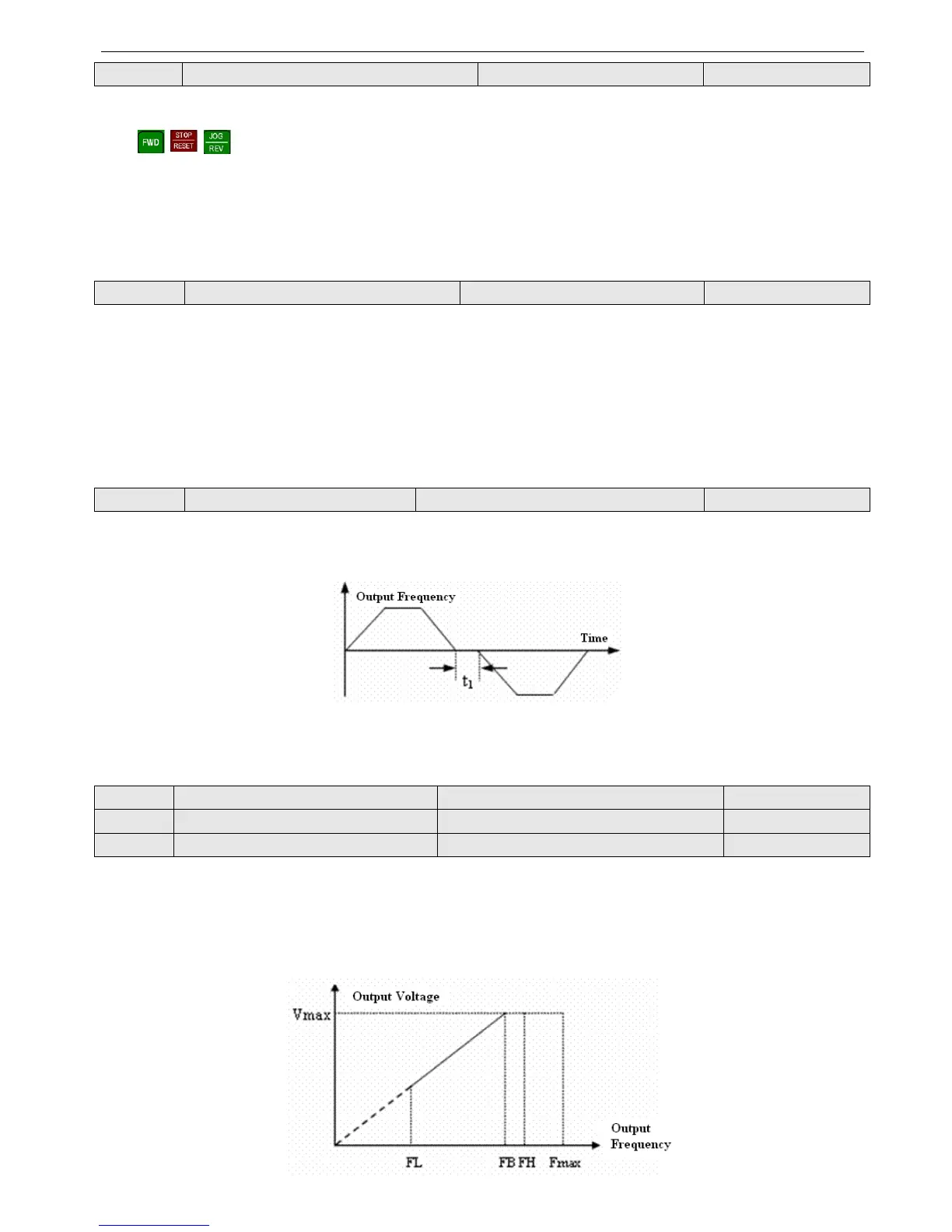
P0.06 Max output frequency Range: 50.00Hz~500.0Hz 50.00Hz
P0.07 Basic running frequency Range: 1.00Hz~500.00Hz 50.00Hz
P0.08 Max output voltage Range: 1~480V Rated
The max output frequency is the highest frequency of the inverter, as shown in Fig.4-2.
Basic running frequency is the lowest frequency when the inverter output the highest voltage and it is usually the rated
frequency of the motor, as shown in Fig4-2 FB.
The max output voltage is the relevant output voltage when the inverter output basic running frequency and it is usually the
rated voltage of the motor, as shown in Fig.4-2 Vmax.