3
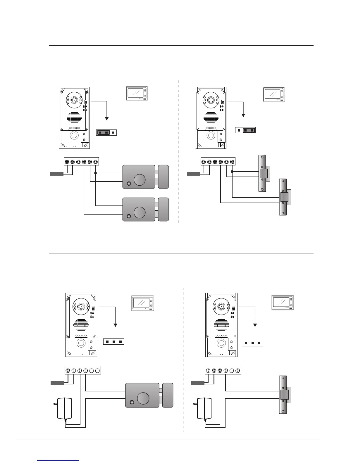
Directlyconnect2electroniclockstothedoorstationandusetheCamerapowertosupplythelocks.Thereare2
separateunlockiconsonMonitorforopeningeachlock.Notethatthe2locksshouldbethesamesafetytype.
Useexternalpowersupplytopowerthelock,inthisway,widerangelockfrom5Vto48Vlockscanbeusedinthe
system.Notethatinthiscase,theLockControlJumperisremovedinbothlocktype.
12
ON
to Monitor
-
+
BUS PL S1+ S2+ S- BUS PL S1+ S2+ S-
-
+
The lock consumption must not
greater than 12V 500mA.
Electromechanical lock
Connection for Electromechanical lock Connection for Electromagnectical lock
lock #2
lock #2
lock #1
lock #1
12
ON
to Monitor
-
+
The lock consumption must not
greater than 12V 300mA.
Electronmagnetical lock
-
+
1 2 3
Jumper position in 1-2
Unlock Mode
0: power-on-to-open
1: power-off-to-open
CALL
UNLOCK
TALK/MON
IN-USE
MENU
1 2 3
Jumper position in 2-3
Unlock Mode
0: power-on-to-open
1: power-off-to-open
CALL
UNLOCK
TALK/MON
IN-USE
MENU
1 2
ON
1 2 3
to Monitor
-
-
+
+
BUS PL S1+ S2+ S- BUS PL S1+ S2+ S-
The lock consumption must not
greater than 48V 1.5A.
1 2
ON
1 2 3
to Monitor
-
+
Jumper removed
The lock consumption must not
greater than 48V 1.5A.
Electronmagnetical lock
Adaptor
-
+
Unlock Mode
0: power-on-to-open
1: power-off-to-open
CALL
UNLOCK
TALK/MON
IN-USE
MENU
Unlock Mode
0: power-on-to-open
1: power-off-to-open
CALL
UNLOCK
TALK/MON
IN-USE
MENU
Electromechanical lock
Connection for Electromechanical lock Connection for Electromagnectical lock
Inner Power 2 Locks Connection
External Power Connection
 Loading...