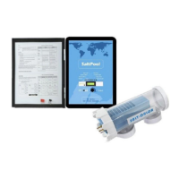
This document serves as the owner's manual and safety instructions for the Xtreme Power Salt Water System Chlorinator, identified by item numbers 90151, 90152, and 90153. It provides comprehensive information on the device's operation, installation, maintenance, and troubleshooting.
Function Description:
The Xtreme Power Salt Water System Chlorinator (SPS) is an automatic chlorine generation system designed for pool and spa sanitation. It converts a low concentration of salt (sodium chloride) in the pool water into free chlorine through electrolysis. This free chlorine effectively kills bacteria and algae, sanitizing the pool. The system is designed to handle the purification needs of an average residential swimming pool up to 40,000 gallons (150,000 liters). The actual amount of chlorination required can vary based on factors such as bather load, rainfall, air temperature, water temperature, pool's exposure to sunlight, pool's surface, and cleanliness. The SPS is not recommended for generating Bromine.
Important Technical Specifications:
The manual outlines critical water chemistry parameters for optimal SPS operation:
- Salt Level: 3200 to 4000 ppm (parts per million), with 3600 ppm being the optimal level.
- Free Chlorine: 1.0 to 3.0 ppm.
- pH: 7.2 to 7.6.
- Cyanuric Acid (Stabilizer): 50 to 100 ppm.
- Total Alkalinity: 80 to 120 ppm.
- Calcium Hardness: 200 to 400 ppm.
- Metals: 0 ppm.
- Saturation Index (Si): -0.2 to 0.2. The Si is calculated as pH + Ti + Ci + Ai - 12.1, where Ti, Ci, and Ai are values derived from water temperature, calcium hardness, and total alkalinity, respectively. An Si below -0.2 indicates corrosive water, while an Si above +0.2 indicates scaling and staining.
- Input Power: The system can operate on 120 VAC or 240 VAC, with jumpers needing to be set for the desired voltage.
- Cell Voltage (typical): 21.0 to 27.0 volts when generating chlorine, otherwise 16-25V.
- Cell Current (typical): 2.50 to 7.80 amps when generating chlorine, otherwise 0 amps.
- Fuse: The circuit board is protected by a 20 amp mini ATO fuse.
- Mounting Distance: The control unit must be mounted a minimum of 5 ft (2 meters) horizontally from the pool/spa.
- Piping: Compatible with 2" (51mm) rigid PVC piping for in-ground pools and 1 1/2-1 1/4 (38-32mm) flexible hose connections for above-ground pools.
- Operating Temperature: The SPS control will not produce chlorine at temperatures below 50°F.
Usage Features:
- Main Switch:
- AUTO: Normal operation, producing chlorine according to the "Desired Level %" setting during the filtering/pumping cycle.
- SUPER CHLORINATE: For high bather loads, heavy rainfall, or cloudy water, this setting electronically "super chlorinates" (shocks) the water for 24 hours (filter pump must be on) or until power is turned off.
- OFF: Prevents the SPS from energizing the electrolytic cell, stopping chlorine generation. For servicing, power should be turned off at the circuit breaker.
- Desired Level Adjustment Knob: Controls chlorine output from 5% to 100% capacity.
- Indicator LEDs:
- POWER: Indicates input power.
- SUPER CHLORINATE: Illuminates during super chlorination.
- REMOTE CONTROLLED: Indicates control by a remote system.
- NO FLOW: Illuminates when no flow is detected, preventing chlorine generation. A flashing LED indicates flow is restored with a 60-second delay before generation resumes.
- CHECK SALT: Flashes for low salt (below 2500ppm) and low efficiency. Steady illumination means salt is too low, and SPS has shut down.
- HIGH SALT: Illuminates when salt is too high, and SPS has shut down. Pool water must be diluted.
- INSPECT CELL: Flashes for reduced cell efficiency or scheduled inspection (after ~500 hours). Steady illumination means greatly reduced efficiency, and SPS has stopped producing chlorine.
- Salt Display: Shows current salt concentration in ppm (or grams/Liter by pressing the "diagnostic" button). Also displays pool water temperature in Fahrenheit (or Celsius by toggling the main switch between AUTO and SUPER CHLORINATE).
- Diagnostic Displays: Sequential presses of the "diagnostic" button provide information on pool temperature, cell voltage, cell current, desired output %, instant salinity, product name, software revision level, and cell type.
- Salt Addition: Salt should be added directly to the shallow end for in-ground pools or in front of the return jet for above-ground pools. It should never be added directly to skimmers or the main drain to prevent damage to the cell.
- Salt Type: Only 99% pure sodium chloride (food quality or water softener salt) should be used. Avoid rock salt, salt with more than 1% yellow prussiate of soda, anti-caking additives, or iodized salt.
- Polymer Use: Recommended to use poly algaecide (30% or 60% concentration) at a rate of 1 quart of Poly30 (or ½ quart of Poly 60) per 15,000 gallons (60,000 liters) monthly, applied in front of the return jet.
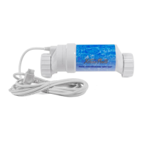
- Installation: The cell and flow switch are plumbed in the return line downstream of all other pool equipment (filter, heater, solar, etc.). The flow switch arrow must point in the direction of water flow.
- Bonding: The SPS enclosure must be bonded with an 8 AWG copper wire (6 AWG Canada) to the pool bonding system.
- Wiring: The SPS should be wired to the LOAD SIDE of the filter pump timer to ensure it only operates when the pump is running. For Canadian models, it must be connected to a circuit protected by a Class A ground fault interrupter.
Maintenance Features:
- Cell Inspection: Recommended every 3 months, or when the "Inspect Cell" LED flashes (after ~500 hours of operation).
- Cell Cleaning:
- First, try flushing with a high-pressure garden hose to remove scale.
- If flushing is insufficient, use a plastic or wood tool to scrape deposits. DO NOT USE METAL SCRAPERS.
- For severe cases, mild acid washing is recommended:
- Mix a 4:1 solution of water to muriatic acid (one gallon of water to one quart of muriatic acid). ALWAYS POUR ACID INTO WATER, NEVER WATER INTO ACID. WEAR PROTECTIVE GLASSES, CLOTHING, AND CHEMICAL-RESISTANT GLOVES.
- Submerge the cell (ensuring the wire harness compartment is not submerged) for five minutes.
- Rinse with a high-pressure garden hose. Repeat if necessary.
- Winterization: The electrolytic cell and flow detection switch must be drained of water in areas prone to freezing temperatures to prevent damage. The electronic control unit does not need to be removed.
- Spring Start-up: Do not turn on the SPS until pool water chemistry has been balanced to proper levels.
- O-Ring Inspection: When replacing the CFT (chlorine generating cell), inspect the O-rings inside the union connections for wear and lubricate them.
- Cell Reversal: It is suggested to reverse the cell's position every time it is cleaned to extend its life.
- Troubleshooting: The manual provides guidance for various LED indicators and diagnostic displays, including "No Flow," "Check Salt," "High Salt," "Inspect Cell," "Power" LED off, "Generating" LED flashing, and "PCB" displayed. It also lists common reasons for insufficient chlorine generation, such as low desired level setting, low stabilizer, short filter pump time, low/high salt, low pH, warm water, cold water, excessive scaling, and high phosphates.