3
to 1-1/2” (38mm) barbed hose adapter is provided to adapt a 1”
(25mm) discharge hose to 1-1/2” (38mm) hose, if desired. The dis-
charge plumbing should be kept as short as possible and bends in
the discharge hose should be kept to a minimum.
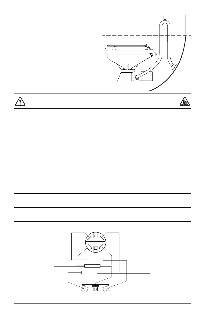
If the toilet is below the water line and is plumbed to an overboard
discharge through hull, the discharge plumbing must include a
vented loop positioned so it remains above the water line at all
angles of heel and trim. Total discharge head should not exceed 4
feet (1.2m). To retain water in the bowl, the discharge hose should
have a vented loop about eight to ten inches above the base of the
toilet and as near to the toilet as can be practically accomplished
without creating an unsightly plumbing situation.
WARNING: FLOOD HAZARD
If toilet is installed below the waterline, it must be installed with a properly positioned vented loop in the
discharge hose. Failure to do so can result in flooding which can cause loss of property and life.
Waterline
BROWN YELLOW
YELLOW
BROWN
RED
YELLOW
BROWN
RED
RED
RED
To waste pump
positive (orange)
motor lead
To solenoid valve
To positive
Vented loop
ELECTRICAL
The electrical wiring should be independent of all other accesso-
ries. It should be made with marine grade copper stranded wire
of the gauge specified in the electrical specifications chart. Make
all wire connections with mechanical locking type connectors
(crimp type butt connectors and terminals). Ensure the circuit is
protected by a proper sized fuse or circuit breaker determined
from the electrical specifications chart. Secure all wires to a solid
surface approximately every eighteen inches (1/2m) along their
entire length of run.
Wire the switch panel to the solenoid valve and toilet pump
assembly as per the following wiring diagram. Select a location
for the switch panel that is convenient to the toilet user and will
also allow access to run the wires from the switch panel to both the
toilet’s motor and the solenoid valve as well as from the electrical
power source to the switch panel. The red lead from the panel
should be connected to an overcurrent protected positive power
source. Connect the brown lead from the panel to the waste pump
positive (orange) motor lead. Connect the black waste pump
motor lead to battery negative. Connect the yellow lead from
the panel to a solenoid valve terminal. Connect the remaining
solenoid valve terminal to battery negative. The solenoid valve is
not polarity sensitive.
To install the switch panel, drill two 1-3/4” (45mm) diameter holes
(slightly over-lapping) through the selected switch mounting
surface per the attached template. Ensure the template is oriented
correctly because it is not symmetrical. Also, drill four appropriate
sized holes for the fasteners selected to secure the switch panel to
its mounting surface.
ELECTRICAL SPECIFICATIONS
WIRING DIAGRAM
* Length of run is total distance from power source to product and back to ground.
Voltage
Amp
Draw
Fuse
Size
Wire Size Per Feet Of Run*
0’-10’ 10’-15’ 15’-25’ 25’-40’ 40’-60’
12 Vdc 10 25 #16 #14 #12 #10 #8
24 Vdc 5 15 #16 #16 #16 #14 #12
 Loading...