en - Original instructions
43
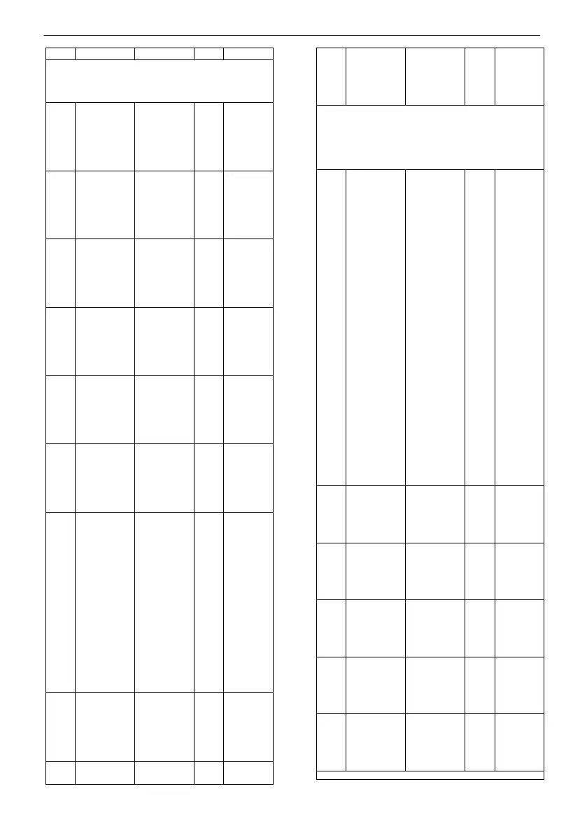
PROGRAMMING DIGITAL INPUTS
(refer to figures 7 and 9)
logic of the
digital input
float switch
G1
Normally
closed
2= NO,
Normally
logic of the
digital input
float switch
G2
Normally
closed
2= NO,
Normally
logic of the
digital input
float switch
G MAX
Normally
closed
2= NO,
Normally
until activa-
input float
switch G
logic of the
digital input
float switch
G MIN
Normally
closed
2= NO,
Normally
until activa-
input float
switch G
tion of pro-
grammable
digital input
(1)
used.
1= External
command
and the
pumps are
switched on
one at a
time (2 sec-
onds apart).
2= External
alarm
3= External
ON/OFF.
4= Change
logic of pro-
grammable
digital input
D IN_PROG
Normally
closed
2= NO,
Normally
grammable
digital input
D IN_PROG
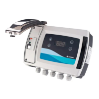
6CP Q-SMART MODULE (OPTION ACCESSO-
RY),
It is an electronic card with six relays and voltage-
free contacts (refer to figures 7, 9).
tion of
OUT_1
relay (K3 on
board)
1= P1 run-
ning
2= P2 run-
ning
3= Fuse 1
burned
4= Fuse 2
burned
5= High
level alarm
6= Alarm
Max level
threshold
7= Alarm
Minimum
level thresh-
old
8= External
alarm
9= Auto-test
in progress.
10= Alarm
sensor fault
11= Power
ON
12=Aut/Man
tion of
OUT_2
relay (K4 on
ration c40
tion of
OUT_3
relay (K5 on
ration c40
tion of
OUT_4
relay (K6 on
ration c40
tion of
OUT_5
relay (K7 on
ration c40
tion of
OUT_6
relay (K8 on
ration c40
 Loading...