5
Wiring Diagram Legends
1. Bold lines indicate action to be taken in Step shown.
2. Grey lines indicate existing wiring.
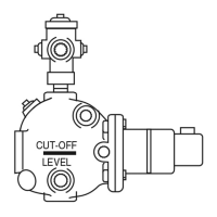
Feeder Model LWCO Model Diagram Number Page
WF2-U-24 PS-802 with burner wiring harness 1 6
WF2-U-24 PS-802 with burner terminal connections 1 6
WF2-U-24 67 w/24 volt burner circuit 4 7
WF2-U-24 67 w/120 volt burner circuit 6 7
WF2-U-24 67G (millivolt burner circuit) 9 8
WF2-U-120 PS-801 with numbered terminals 2 6
WF2-U-120 PS-801 with lettered terminals 3 6
WF2-U-120 67 w/24 volt burner circuit 7 8
WF2-U-120 67 w/120 volt burner circuit 5 7
WF2-U-120 67G (millivolt burner circuit) 8 8
WF2-U-24 Hydrolevel 400 10 9
WF2-U-24 Hydrolevel CG400 11 9
WF2-U-120 Hydrolevel 450 12 9
WF2-U-120 Hydrolevel CG450 13 10
WF2-U-120 Hydrolevel CGT450 14 10
WF2-U-24 Honeywell LWCO (24 volt) 15 10
WF2-U-120 Honeywell LWCO (120 volt) 16 11
WF2-U-24 TACO LWCO (24 volt) 18 11
WF2-U-120 TACO LWCO (120 volt) 17 11
Wiring Diagram Selection Chart
Do not use automatic water feeders with manual
reset LWCO's. Failure to follow this warning could
cause flooding, property damage, personal injury
or death.
WARNING
Unless otherwise noted, water feeder voltage
should be the same as the LWCO and burner
circuit voltage.
NOTE
Before connecting water feeder, operate boiler and
check all safety devices.
NOTE
Based on the water feeder and low water cut-off combination you are installing, select proper wiring
diagram and proceed to that page.

 Loading...