EasyManua.ls Logo

Yaesu FC-102 User Manual

Yaesu FC-102
21 pages
To Next Page IconTo Next Page
Page #1 background imageLoading...
Page #1 background image
Message from:
Amateur Radio Station VA3VFO
Greg White, owner/operator
Re. Yaesu, Model 102 Series, Amateur Radio Equipment
Greetings from Toronto, Canada! I hope you will find the attached Yaesu manual
helpful. I have been assisted many times, by Hams whom have kindly made manuals
available for free via mail and the Internet. I would like to take this
opportunity to now make a contribution of my own.
I have noted the famous Yaesu Model 102 Series of radio equipment manuals absent
from the Internet. I am a happy owner of a complete Yaesu 102 station and in
possession of its manuals. Hearing of many requests for the manuals, I have
scanned my collection and present it to you here, free of charge. I do so with
the hope that it will assist you in keeping your own Yaesu 102 equipment running
forever and as correctly intended by the factory. I also realize how frustrating
it can be trying to remember the forgotten instructions of a destroyed or
misplaced manual!
I request that these files remain free for private distribution and personal use
by fellow licensed Amateur Radio Operators only and that they are to be
considered as if "on loan". No fees are to be charged for, or as a result of
their use, nor are they to be published publicly. They are provided for private
personal reference only and if shared with other Hams, I ask that the credit for
the scanning and free "loan" remain with me.
I look forward to your continued support of the excellent FT102 Transceiver and
Accessories and helping to build both its continued demand as a "collectable" and
its assured respect in Amateur Radio history.
73
yours truly,
Greg White
VA3VFO
Toronto, CANADA
va3vfo@rac.ca
Question and Answer IconNeed help?

Do you have a question about the Yaesu FC-102 and is the answer not in the manual?

Yaesu FC-102 Specifications

General IconGeneral
Power Handling150 W
Impedance50 ohms
Tuning MethodManual
Dimensions10.9 x 3.9 x 10.6 in
Weight6.4 lbs
Output Impedance50 ohms
TypeAntenna Tuner
Power Rating150 W

Summary

General Description

Specifications and Accessories

Specifications

Technical details including frequency range, power, and impedance matching capabilities.

Accessories

Lists included accessories such as connection cables and foot.

Front Panel Controls and Switches

TUNE Control

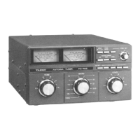
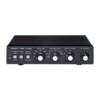
Matches impedance of FC-102 and antenna system to transmitter.

BAND Selector

Adjusts inductance for antenna system; THRU bypasses tuner.

LOAD Control

Adjusts capacitance to match antenna to inductance and TUNE settings.

ANT Push Buttons

Selects between ANT A/B terminals or FAS-1-4R antenna selector.

FWD SET Knob

Sets SWR meter to full scale before measuring reflected power.

Push Button Switches

Selects input (A/B), holds peak meter reading, and sets SWR meter.

METER RANGE Buttons

Selects the full scale range for the FWD POWER meter.

FWD POWER Meter

Indicates forward RMS or peak power based on meter switch setting.

SWR Meter

Indicates reflected power for SWR measurement during tuning.

Rear Panel Connectors

INPUT A and B Jacks

Coaxial jacks for connecting transmitter/linear amplifier inputs.

ANTENNA A, B, and WIRE Terminals

Coaxial jacks for antenna connection, includes WIRE terminal.

GND Terminal

Terminal for connection to earth ground for safety.

METER Switch

Selects RMS or peak (PEP) indication on the FWD POWER meter.

REMOTE Terminal Strip

For switching control signals for optional FAS-1-4R Antenna Selector Unit.

DC 12V Connector

Connector for receiving 12 volts for meter lamps and relay switching.

FAS-1-4R Subpanel

Panel for internal installation of the optional FAS-1-4R Antenna Selector.

Installation and Interconnections

Interconnections Diagram

Diagram showing how to connect the FC-102 to a transceiver and antenna system.

Installation Caution

Warning regarding connection to the WIRE terminal during transmission.

Operation

Antenna Matching with Dummy Load

Procedure for matching antennas using a dummy load for optimal tuning.

Antenna Matching without Dummy Load

Procedure for matching antennas without a dummy load, with safety advice.

Antenna Matching for Solid State Transmitters

Procedure for matching antennas with solid state transceivers and linear amplifiers.

Recording Tune and Load Positions

Guidance on recording optimal TUNE and LOAD control positions for antennas.

SWR Measurement

Procedure for accurately measuring SWR using the FC-102.

Forward Power Measurement

Procedure for accurately measuring forward output power using the FC-102.

Receive Operation

Procedure for tuning antennas for shortwave broadcast reception.

Alignment

Power Meter Calibration

Steps for calibrating the power meter using a reference wattmeter.

FWD POWER Meter Zeroing

Procedure for zeroing the FWD POWER meter.

FAS-1-4R Antenna Selector Installation

FAS-1-4R Installation in FC-102

Instructions for installing the FAS-1-4R module inside the FC-102 unit.

FAS-1-4R Interconnection at Remote Location

Instructions for connecting the FAS-1-4R at a remote location.

Parts List

Main Chassis Parts

List of components for the main chassis of the FC-102.

Peak-Hold Unit Parts

List of components for the peak-hold unit of the FC-102.

Related product manuals