The Yaesu FL-110 is an all solid-state linear amplifier designed to enhance the performance of FT-301S and FT-7 transceivers across the amateur radio bands from 160 through 10 meters.
Function Description
The FL-110 serves as a broad-band linear amplifier, utilizing a push-pull configuration with a pair of SRF-1427 transistors. This design incorporates negative feedback to minimize distortion and spurious radiation, ensuring a clean output signal. A key feature is the Automatic Level Control (ALC) circuit, which manages the exciter gain to achieve the highest average power without peak clipping distortion. This ALC also protects the PA transistors from damage due to overdrive. The amplifier includes an internal change-over relay that operates automatically, triggered by either a transmitted signal or the PTT (Push-To-Talk) switch from the exciter.
Important Technical Specifications
- Circuit Type: Transistorized push-pull, wide-band linear amplifier.
- Frequency Coverage: Ham bands 160 through 10 meters.
- Wave Forms Supported: SSB, AM, CW, and FSK.
- Maximum Drive Power:
- 15 watts for CW, SSB
- 4 watts for AM, FSK
- Input Impedance: 50 ohms unbalanced.
- Output Impedance: 50 ohms unbalanced.
- Maximum Input Power:
- 200 watts DC for SSB, CW
- 75 watts DC for FSK
- 50 watts DC for AM
- Distortion: Better than 31 dB.
- Spurious Radiation: Less than -40 dB.
- Power Requirement: 13.5V DC ±10% negative ground.
- Receive: 0.05 amps
- Transmit: 17 amps at 100 watts output at 14 MHz
- Size: 120(W) x 100(H) x 200(D) mm.
- Weight: 2.5 kg.
- Semiconductor Complement:
- IC: μPC271C (1)
- Transistors (TR): 2SC372Y (1), 2SC735Y (1), 2SD235 (1), SRF1427 (2)
- Diodes: 1S-1007 (12), 10D1 (3), 10D10 (2), SG103D (1), SR103D (2), CW01B (1)
Usage Features
The FL-110 is designed for straightforward installation and operation, requiring only a 13.5V DC power source and an antenna.
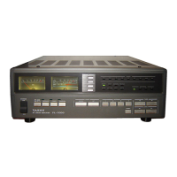
- Front Panel Controls & Indicators:
- POWER Switch: Turns the amplifier power "ON".
- DELAY Switch: Selects the relay hold time for carrier-operated change-over. "FAST" provides 0.1-0.2 seconds, while "SLOW" provides 0.3-1.0 seconds.
- BAND Switch: Selects the amateur band between 160 and 10 meters.
- REC Indicator (Green Lamp): Indicates receive mode.
- OPER Indicator (Red Lamp): Indicates transmit mode.
- AFP Indicator (Red Lamp): Lights up when the Automatic Final Protection (AFP) circuit is active, indicating the linear amplifier is shut down due to a problem (e.g., defective antenna system or overdrive).
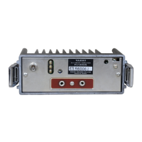
- Rear Panel Connectors & Controls:
- INPUT Connector: Input for the drive signal from the exciter.
- ANT Connector: Antenna connector.
- POWER Input: DC-13.5V, 20A power input.
- PTT Terminal: External PTT control terminal, with a switch to select relay polarity (negative for FT-101 series, positive for FT-301 series).
- GND Terminal: Ground connection.
- Keying Options: The amplifier can be keyed manually via the transceiver's accessory relay output or automatically by VOX (voice-controlled) mode from the transceiver.
- Automatic Operation: When the power switch is "OFF," the FL-110 is bypassed, and the antenna is directly connected to the transceiver. When "ON," the green REC lamp lights up, and the amplifier is keyed with the transceiver, with the red OPER lamp indicating transmit mode.
- Low Power Operation: The carrier-operated change-over circuit may not function with driving power less than 1 watt.
Maintenance Features
The FL-110 is designed for reliability, but certain precautions and realignment procedures are outlined.
- Installation Precautions:
- Ensure the DC power source is 13.5V and does not exceed 14V.
- Connect the ORANGE lead to positive (+) and the BLACK lead to negative (-) to prevent permanent damage from incorrect polarity.
- Use a short power cable to minimize voltage drop and provide a low impedance path.
- In mobile installations, verify the automobile's voltage regulator setting does not exceed 14V.
- Install the FL-110 with the heat sink on top to ensure adequate ventilation and avoid excessively warm locations (e.g., car heater ducts).
- Ensure the antenna presents a 50-ohm non-reactive load. An SWR of 2:1 will reduce output power, and an SWR of 3:1 will activate the AFP circuit to protect the PA transistor.
- Operating Precautions:
- Do not exceed the rated drive power of 15 watts.
- Do not key the FL-110 without a proper antenna connected.
- Disconnect the power cable from the battery if the FL-110 will not be used for several months, as the PA transistor collector draws 5 milliamps even when the power switch is "OFF."
- AFP Circuit Reset: If the AFP circuit activates (red AFP lamp lights), turn the power switch "OFF," identify and resolve the cause (defective antenna or overdrive), then turn the power switch "ON" to reset the circuit.
- Realignment Procedures (typically only required after service or component replacement):
- DELAY Adjustment (VR201): Adjust VR201 clockwise for a longer relay hold time.
- BALANCE Adjustment of CM Coupler (TC101, TC301):
- Set power switch to "OFF." Connect a dummy load/wattmeter to the antenna.
- Apply 10 watts CW on 3.5 MHz from the exciter.
- Connect a VTVM between "R" (+) and ground (-) on the control unit. Adjust TC101 for a minimum VTVM reading (<0.05V).
- Connect VTVM (+) to TP301 on the LPF unit. Set power switch to "ON." Adjust TC301 for a minimum VTVM reading (<0.1V).
- AFP Circuit Adjustment (VR202, VR203, VR301):
- Set VR202 and VR301 fully clockwise, and VR203 fully counter-clockwise.
- Connect dummy load/wattmeter. Apply 3.5 MHz 20 watts carrier.
- Slowly advance VR202 counter-clockwise until the AFP relay activates.
- Turn power "OFF," set exciter to 15 watts, then "ON." The AFP should not activate. If it does, slowly advance VR203 clockwise.
- Repeat with 20 watts input (AFP should activate) and 15 watts input (AFP should not activate).
- Rotate VR301 counter-clockwise until AFP activates, then back 5 degrees clockwise.
- Connect VSWR meter, antenna coupler, and dummy load/wattmeter. Transmit on 3.5 MHz, adjust exciter output and antenna coupler for 1:3 VSWR at 70 watts output. Slowly rotate VR203 clockwise until AFP activates.
- CARRIER CONTROL CIRCUIT Adjustment (VR101):
- Disconnect PTT. Set VR101 fully clockwise. Turn power "ON."
- Apply 3.5 MHz 10 watts CW. Slowly rotate VR101 counter-clockwise until the relay activates. Reconnect PTT.
- PA BIAS Adjustment (VR1201): Only required if PA power transistors are replaced.
- Connect a 1A ammeter in the power supply line (cut red wire).
- Disconnect exciter. Set PTT switch to (-). Connect PTT terminal (pin 4) to ground.
- Turn power "ON." Adjust VR1201 for 100mA idle current.
- Remove ammeter and restore wiring.